INVERTER WITH CONVERTER REMOVAL
PROCEDURE
-
PRECAUTION
-
REMOVE SERVICE PLUG GRIP
-
REMOVE NO. 1 ENGINE UNDER COVER ASSEMBLY
-
DRAIN COOLANT (for Inverter)
-
DISCONNECT INVERTER COOLING HOSE (for RHD)
Note
-
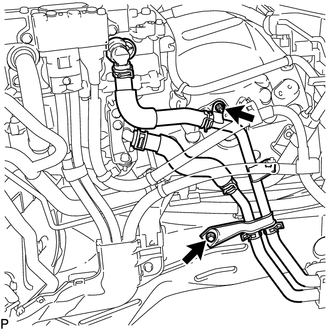
Be sure to drain the coolant (for inverter) by disconnecting the No. 4 inverter cooling hose and No. 5 inverter cooling hose before removing the inverter with converter assembly. The coolant (for inverter) cannot be drained completely by just removing the radiator drain cock plug.
-
Collect the drained coolant (for inverter) and measure its volume to establish a benchmark. Measure the amount of coolant (for inverter) drained from the radiator drain cock plug, No. 4 inverter cooling hose and No. 5 inverter cooling hose. Make sure to add more coolant (for inverter) than measured.
-
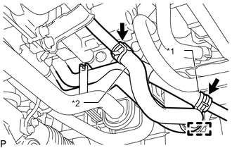
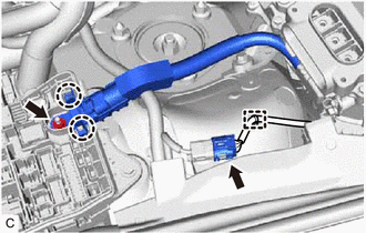
*1 No. 4 Inverter Cooling Hose *2 No. 5 Inverter Cooling Hose Disengage the clamp from the inlet inverter cooling pipe.
Note
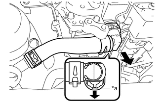
Do not remove the clamp from the No. 5 inverter cooling hose.
-
Slide the clip and disconnect the No. 5 inverter cooling hose from the inlet inverter cooling pipe.
Note
Put pieces of cloth into the pipe and disconnected hose or cover the pipe and hose with plastic bags to prevent entry of foreign matter.
-
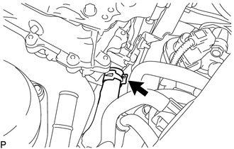
Slide the clip and disconnect the No. 4 inverter cooling hose from the inlet inverter cooling pipe.
Note
Put pieces of cloth into the pipe and disconnected hose or cover the pipe and hose with plastic bags to prevent entry of foreign matter.
-
-
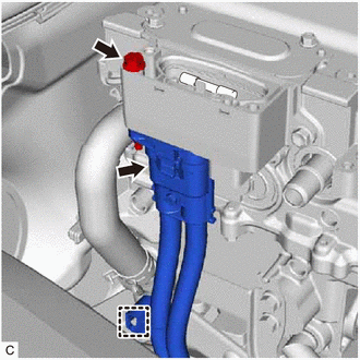
REMOVE CONNECTOR COVER ASSEMBLY
CAUTION:
Wear insulated gloves.
-
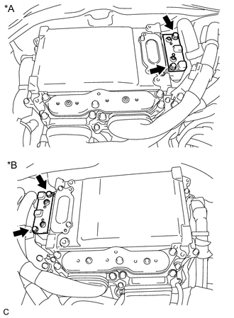
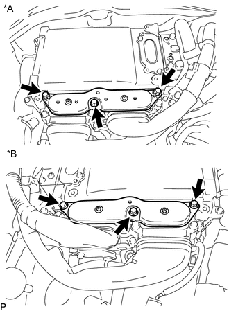
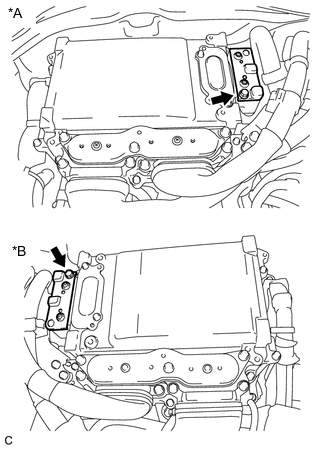
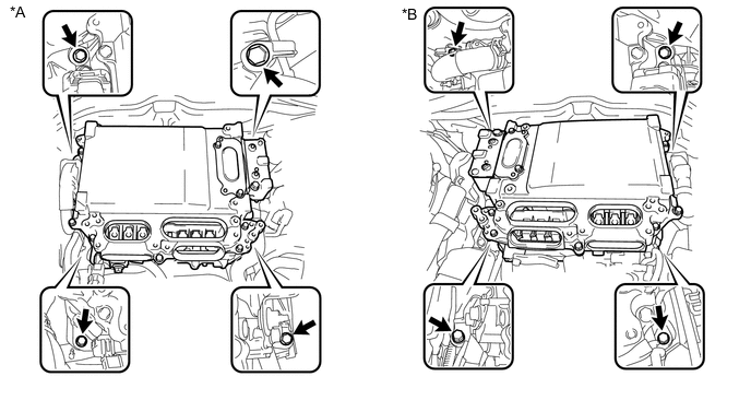
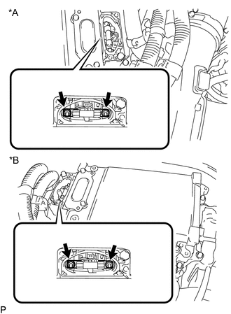
*A for LHD *B for RHD Remove the 2 bolts and connector cover assembly from the inverter with converter assembly.
Note
-
Make sure to pull the connector cover assembly straight up, as a connector is connected to the bottom of the cover.
-
Do not touch the connector cover assembly waterproofing rubber.
-
Do not allow any foreign matter or water to enter the inverter with converter assembly.
-
-
-
CHECK TERMINAL VOLTAGE
CAUTION:
Wear insulated gloves.
Note
Do not allow any foreign matter or water to enter the inverter with converter assembly.
-
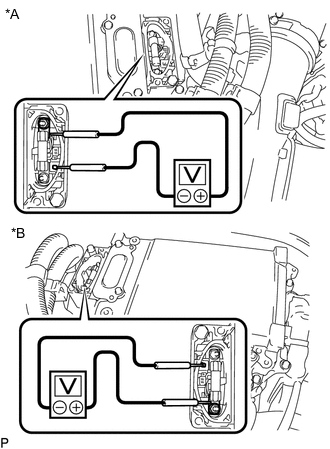
*A for LHD *B for RHD Using a voltmeter, measure the voltage between the terminals of the 2 phase connectors.
Standard Voltage 0 V Tech Tips
Use a measuring range of DC 750 V or more on the voltmeter.
-
-
TEMPORARILY INSTALL CONNECTOR COVER ASSEMBLY
CAUTION:
Wear insulated gloves.
-

*A for LHD *B for RHD Temporarily install the connector cover assembly with the bolt to prevent any foreign matter or water from entering the inverter with converter assembly.
Note
-
Visually confirm that the connector cover assembly waterproofing rubber is securely installed before installing the connector cover assembly.
-
Do not touch the connector cover assembly waterproofing rubber.
-
Make sure that the interlock is fully engaged.
-
-
-
REMOVE INVERTER MOTOR CABLE BRACKET ASSEMBLY
-
*A for LHD *B for RHD Disengage the 2 clamps from the inverter motor cable bracket assembly.
-
Remove the 2 bolts and inverter motor cable bracket from the inverter with converter assembly.
-
-
REMOVE INVERTER TERMINAL COVER
CAUTION:
Wear insulated gloves.
-
*A for LHD *B for RHD Remove the 3 bolts and inverter terminal cover from the inverter with converter assembly.
Note
-
Make sure to pull the inverter terminal cover straight up, as a connector is connected to the bottom of the cover.
-
Do not touch the inverter terminal cover waterproofing rubber.
-
Do not allow any foreign matter or water to enter the inverter with converter assembly.
-
-
-
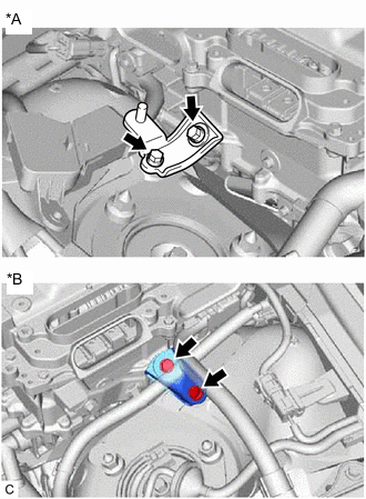
DISCONNECT MOTOR CABLE
CAUTION:
Wear insulated gloves.
-
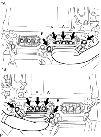
*A for LHD *B for RHD Using an insulated tool, remove the 3 bolts (A).
-
Using an insulated tool, remove the 2 bolts (B), and disconnect the motor cable from the inverter with converter assembly.
Note
-
Do not allow any foreign matter or water to enter the inverter with converter assembly.
-
Do not touch the connector waterproofing rubber or terminals.
-
Do not damage the terminals, connector housings or inverter with converter assembly during disconnection.
-
Insulate the disconnected terminals with insulating tape.
-
Cover the hole where the cable was connected with tape (non-residue type) or equivalent to prevent entry of foreign matter.
-
-
-
DISCONNECT GENERATOR CABLE
CAUTION:
Wear insulated gloves.
-
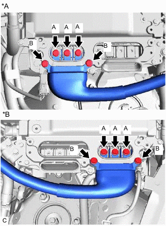
*A for LHD *B for RHD Using an insulated tool, remove the 3 bolts (A).
-
Using an insulated tool, remove the 2 bolts (B), and disconnect the generator cable from the inverter with converter assembly.
Note
-
Do not allow any foreign matter or water to enter the inverter with converter assembly.
-
Do not touch the connector waterproofing rubber or terminals.
-
Do not damage the terminals, connector housings or inverter with converter assembly during disconnection.
-
Insulate the disconnected terminals with insulating tape.
-
Cover the hole where the cable was connected with tape (non-residue type) or equivalent to prevent entry of foreign matter.
-
-
-
DISCONNECT AIR CONDITIONING HARNESS (for RHD)
-
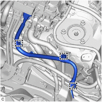
Disengage the 3 clamps.
-
-
SEPARATE INLET INVERTER COOLING PIPE (for RHD)
-
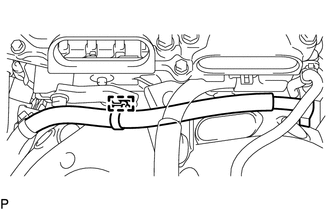
Remove the bolt and nut from the inlet inverter cooling pipe.
-
Separate the inlet inverter cooling pipe.
Note
Before disconnecting the inlet No. 2 inverter cooling hose, disconnect the inlet inverter cooling pipe to prevent excessive force from being applied when disconnecting the inlet No. 2 inverter cooling hose.
-
-
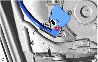
DISCONNECT OUTLET NO. 1 INVERTER COOLING HOSE (for LHD)
-
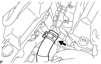
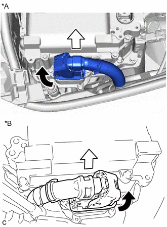
*a Retainer Release the retainer and disconnect the outlet No. 1 inverter cooling hose from the inverter with converter assembly as shown in the illustration.
Note
Put pieces of cloth into the pipe and disconnected hose or cover the pipe and hose with plastic bags to prevent entry of foreign matter.
-
-
DISCONNECT INLET NO. 1 INVERTER COOLING HOSE (for LHD)
-
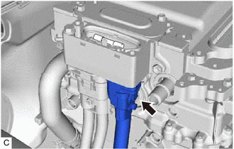
Slide the clip and disconnect the inlet No. 1 inverter cooling hose from the inverter with converter assembly.
Note
Put pieces of cloth into the pipe and disconnected hose or cover the pipe and hose with plastic bags to prevent entry of foreign matter.
-
-
DISCONNECT OUTLET NO. 2 INVERTER COOLING HOSE (for RHD)
-
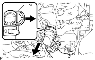
*a Retainer Release the retainer and disconnect the outlet No. 2 inverter cooling hose from the inverter with converter assembly as shown in the illustration.
Note
Put pieces of cloth into the pipe and disconnected hose or cover the pipe and hose with plastic bags to prevent entry of foreign matter.
-
-
DISCONNECT INLET NO. 2 INVERTER COOLING HOSE (for RHD)
-
Slide the clip and disconnect the inlet No. 2 inverter cooling hose from the inverter with converter assembly.
Note
Put pieces of cloth into the pipe and disconnected hose or cover the pipe and hose with plastic bags to prevent entry of foreign matter.
-
-
REMOVE CONNECTOR COVER ASSEMBLY
CAUTION:
Wear insulated gloves.
-
*A for LHD *B for RHD Remove the bolt and connector cover assembly from the inverter with converter assembly.
Note
-
Make sure to pull the connector cover assembly straight up, as a connector is connected to the bottom of the cover.
-
Do not touch the connector cover assembly waterproofing rubber.
-
Do not allow any foreign matter or water to enter the inverter with converter assembly.
-
-
-
DISCONNECT AIR CONDITIONING HARNESS (for RHD)
CAUTION:
Wear insulated gloves.
-
Disconnect the air conditioning harness connector from the inverter with converter assembly.
Note
-
Do not allow any foreign matter or water to enter the inverter with converter assembly.
-
Do not touch the connector waterproofing rubber or terminals.
-
Do not damage the connector, connector housing or inverter with converter assembly during disconnection.
-
Insulate the disconnected terminals with insulating tape.
-
Cover the hole where the cable was connected with tape (non-residue type) or equivalent to prevent entry of foreign matter.
-
-
-
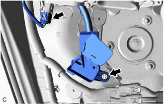
DISCONNECT FRAME WIRE
CAUTION:
Wear insulated gloves.
-
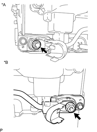
for LHD:
-
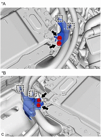
Remove the bolt and disconnect the 2 frame wire connectors from the inverter with converter assembly.
Note
-
Do not allow any foreign matter or water to enter the inverter with converter assembly.
-
Do not touch the connector waterproofing rubber or terminals.
-
Do not damage the connectors, connector housings or inverter with converter assembly during disconnection.
-
Insulate the disconnected terminals with insulating tape.
-
Cover the hole where the cable was connected with tape (non-residue type) or equivalent to prevent entry of foreign matter.
-
-
-
for RHD:
-
Disengage the clamp.
-
Remove the bolt and disconnect the frame wire connector from the inverter with converter assembly.
Note
-
Do not allow any foreign matter or water to enter the inverter with converter assembly.
-
Do not touch the connector waterproofing rubber or terminals.
-
Do not damage the connector, connector housing or inverter with converter assembly during disconnection.
-
Insulate the disconnected terminals with insulating tape.
-
Cover the hole where the cable was connected with tape (non-residue type) or equivalent to prevent entry of foreign matter.
-
-
-
-
TEMPORARILY INSTALL CONNECTOR COVER ASSEMBLY
-
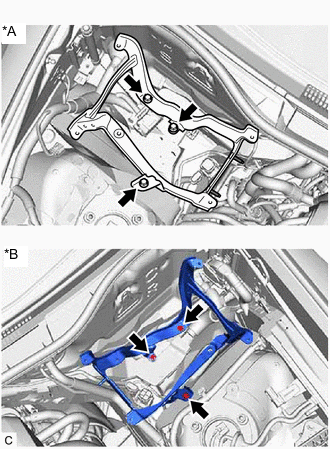
REMOVE NO. 6 INVERTER BRACKET
-
*A for LHD *B for RHD Remove the 2 bolts and No. 6 inverter bracket.
-
-
REMOVE INVERTER WITH CONVERTER ASSEMBLY
CAUTION:
Wear insulated gloves.
-
for LHD:
-
Open the inverter bus-bar plate sub-assembly cover.
-
Remove the nut and disconnect the engine room main wire from the inverter bus-bar plate sub-assembly.
-
Remove the nut and disconnect the inverter bus-bar plate sub-assembly.
-
Disconnect the inverter with converter assembly connector.
-
-
for RHD:
-
Remove the No. 1 relay block cover from the engine room relay block and junction block assembly.
-
Remove the nut from the inverter bus-bar plate sub-assembly.
-
Disengage the 2 claws and disconnect the inverter bus-bar plate sub-assembly from the engine room relay block and junction block assembly.
-
Disconnect the inverter with converter assembly connector and disengage the clamp.
Tech Tips
If the clamp is damaged when disconnecting it, it is not necessary to reconnect it to the vehicle body.
-
Disengage the wiring harness clamp.
-
-
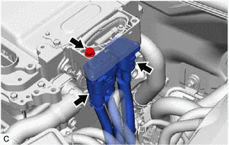
*A for LHD *B for RHD Raise the lock lever and disconnect the inverter with converter assembly connector from the inverter with converter assembly as shown in the illustration.
Note
-
Insulate the disconnected connector with insulating tape.
-
Cover the hole where the connector was connected with tape (non-residue type) or equivalent to prevent entry of foreign matter.
-
-
Remove the 4 bolts and inverter with converter assembly.
*A for LHD *B for RHD Note
-
Since the inverter with converter assembly is very heavy, 2 people are needed to remove the inverter with converter assembly. When removing the inverter with converter assembly, do not damage the parts around it.
-
To prevent damage, do not hold the inverter with converter assembly by the connectors.
-
To prevent damage due to static electricity, do not touch the terminals of the disconnected connectors.
-
Cover the connectors with insulating tape to prevent foreign matter or water from entering.
Tech Tips
Even after the coolant is drained, coolant remains in the inverter due to its internal structure. Therefore, seal or cover the pipes when removing the inverter so that coolant does not spill out.
-
-
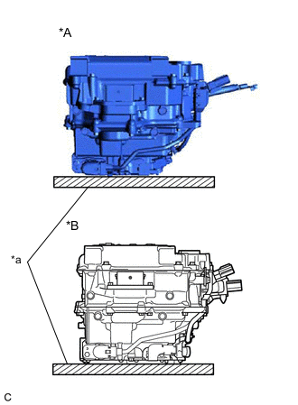
*A for LHD *B for RHD *a Wooden Block Place the inverter with converter assembly on a wooden block.
Note
If the removed inverter with converter assembly is to be stored, make sure to seal the openings of the connector cover assembly and inverter with converter assembly with tape (non-residue type) to prevent entry of foreign matter and water.
-
-
REMOVE NO. 4 INVERTER BRACKET
-
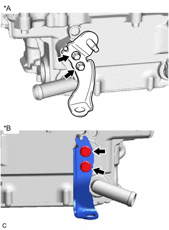
*A for LHD *B for RHD Remove the 2 bolts and No. 4 inverter bracket from the inverter with converter assembly.
-
-
REMOVE WIRING HARNESS CLAMP BRACKET (for RHD)
-
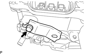
Remove the bolt and wiring harness clamp bracket from the inverter with converter assembly.
-
-
REMOVE INVERTER BUS-BAR PLATE SUB-ASSEMBLY
-
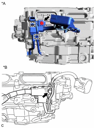
*A for LHD *B for RHD Disengage the 2 clamps from the inverter bus-bar plate sub-assembly.
-
Remove the bolt.
-
*A for LHD *B for RHD Open the terminal cover.
-
Remove the nut.
Note
If the stud bolt becomes loose when removing the nut, tighten the stud bolt to a torque of 10 N*m (102 kgf*cm 7 ft.*lbf).
-
Remove the inverter bus-bar plate sub-assembly from the inverter with converter assembly.
Note
If the inverter bus-bar plate sub-assembly is dropped or deformed, replace it with a new one.
-
-
REMOVE HIGH VOLTAGE FUSE
CAUTION:
Wear insulated gloves.
Tech Tips
Perform this procedure only when replacement of the high voltage fuse is necessary.
-
Remove the connector cover assembly.
Click here
-
*A for LHD *B for RHD Remove the 2 nuts and high voltage fuse from the inverter with converter assembly.
Note
Do not allow any foreign matter or water to enter the inverter with converter assembly.
-
Temporarily install the connector cover assembly.
-
-
REMOVE NO. 1 INVERTER COOLING HOSE
Tech Tips
Perform this procedure only when replacement of the No. 1 inverter cooling hose is necessary.
-
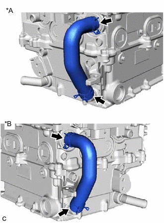
*A for LHD *B for RHD Slide the 2 clips and remove the No. 1 inverter cooling hose from the inverter with converter assembly.
Note
Put pieces of cloth into the pipes or cover the pipes with plastic bags to prevent entry of foreign matter.
-
-
REMOVE NO. 5 INVERTER BRACKET
Tech Tips
Perform this procedure only when replacement of the No. 5 inverter bracket is necessary.
-
Remove the power steering ECU assembly (for LHD).
-
Remove the power steering ECU assembly (for RHD).
-
*A for LHD *B for RHD Remove the 3 bolts and No. 5 inverter bracket.
-