RELAY ON-VEHICLE INSPECTION
PROCEDURE
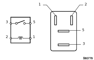
INSPECT CIRCUIT OPENING RELAY (C/OPN)
-
Measure the resistance according to the value(s) in the table below.
Standard Resistance
Tester Connection
Condition
Specified Condition
3 - 5
Battery voltage is not applied to terminals 1 and 2
10 kΩ or higher
Battery voltage is applied to terminals 1 and 2
Below 1 Ω
If the result is not as specified, replace the circuit opening relay.
-
INSPECT AIR INJECTION VSV RELAY (AI-VSV)
-
Measure the resistance according to the value(s) in the table below.
Standard Resistance
Tester Connection
Condition
Specified Condition
3 - 5
Battery voltage is not applied to terminals 1 and 2
10 kΩ or higher
Battery voltage is applied to terminals 1 and 2
Below 1 Ω
If the result is not as specified, replace the air injection VSV relay.
-
INSPECT STARTER RELAY (ST)
-

Measure the resistance according to the value(s) in the table below.
Standard Resistance
Tester Connection
Condition
Specified Condition
3 - 5
Battery voltage is not applied to terminals 1 and 2
10 kΩ or higher
Battery voltage is applied to terminals 1 and 2
Below 1 Ω
If the result is not as specified, replace the starter relay.
-
INSPECT FUEL PUMP RELAY (w/o Heated Windshield Defroster System (FUEL PMP))
-
Measure the resistance according to the value(s) in the table below.
Standard Resistance
Tester Connection
Condition
Specified Condition
3 - 5
Battery voltage is not applied to terminals 1 and 2
10 kΩ or higher
Battery voltage is applied to terminals 1 and 2
Below 1 Ω
If the result is not as specified, replace the fuel pump relay.
-
INSPECT AIR PUMP HEATER RELAY (w/ Heated Windshield Defroster System (AIR PMP HTR))
-

Measure the resistance according to the value(s) in the table below.
Standard Resistance
Tester Connection
Condition
Specified Condition
3 - 5
Battery voltage is not applied to terminals 1 and 2
10 kΩ or higher
Battery voltage is applied to terminals 1 and 2
Below 1 Ω
If the result is not as specified, replace the air pump heater relay.
-
INSPECT NO. 1 INTEGRATION RELAY (w/o Heated Windshield Defroster System (IG2))
Check the IG2 fuse.
Measure the resistance according to the value(s) in the table below.
Standard Resistance
Tester Connection
Condition
Specified Condition
IG2 fuse
Always
Below 1 Ω
If the result is not as specified, replace the IG2 fuse.
Check the IG2 relay.
-

*a
Component without harness connected
(Integration Relay)
Measure the resistance according to the value(s) in the table below.
Standard Resistance
Tester Connection
Condition
Specified Condition
1C-1 - 1A-4
Battery voltage not applied to terminals 1A-1 and 1A-3
10 kΩ or higher
Battery voltage applied to terminals 1A-1 and 1A-3
Below 1 Ω
If the result is not as specified, replace the No. 1 integration relay.
-
INSPECT NO. 1 INTEGRATION RELAY (w/o Heated Windshield Defroster System (EFI))
Check the EFI fuse.
Measure the resistance according to the value(s) in the table below.
Standard Resistance
Tester Connection
Condition
Specified Condition
EFI fuse
Always
Below 1 Ω
If the result is not as specified, replace the EFI fuse.
Check the EFI relay.
-
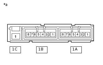
*a
Component without harness connected
(Integration Relay)
Measure the resistance according to the value(s) in the table below.
Standard Resistance
Tester Connection
Condition
Specified Condition
1C-1 - 1B-4
Battery voltage not applied to terminals 1B-2 and 1B-3
10 kΩ or higher
Battery voltage applied to terminals 1B-2 and 1B-3
Below 1 Ω
If the result is not as specified, replace the No. 1 integration relay.
-
INSPECT NO. 1 INTEGRATION RELAY (w/o Heated Windshield Defroster System (A/F))
Check the A/F fuse.
Measure the resistance according to the value(s) in the table below.
Standard Resistance
Tester Connection
Condition
Specified Condition
A/F fuse
Always
Below 1 Ω
If the result is not as specified, replace the A/F fuse.
Check the A/F relay.
-

*a
Component without harness connected
(Integration Relay)
Measure the resistance according to the value(s) in the table below.
Standard Resistance
Tester Connection
Condition
Specified Condition
1C-1 - 1B-8
Battery voltage not applied to terminals 1B-4 and 1B-7
10 kΩ or higher
Battery voltage applied to terminals 1B-4 and 1B-7
Below 1 Ω
If the result is not as specified, replace the No. 1 integration relay.
-
INSPECT NO. 1 INTEGRATION RELAY (w/ Heated Windshield Defroster System (IG2))
Check the IG2 fuse.
Measure the resistance according to the value(s) in the table below.
Standard Resistance
Tester Connection
Condition
Specified Condition
IG2 fuse
Always
Below 1 Ω
If the result is not as specified, replace the IG2 fuse.
Check the IG2 relay.
Measure the resistance according to the value(s) in the table below.
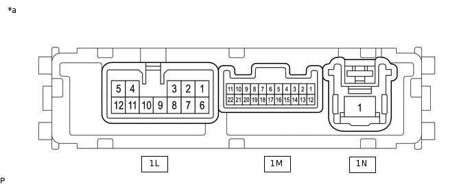
*a
Component without harness connected
(Integration Relay)
-
-
Standard Resistance
Tester Connection
Condition
Specified Condition
1N-1 - 1L-6
Battery voltage not applied to terminals 1M-16 and 1M-4
10 kΩ or higher
Battery voltage applied to terminals 1M-16 and 1M-4
Below 1 Ω
If the result is not as specified, replace the No. 1 integration relay.
INSPECT NO. 1 INTEGRATION RELAY (w/ Heated Windshield Defroster System (EFI MAIN))
Check the EFI fuse.
Measure the resistance according to the value(s) in the table below.
Standard Resistance
Tester Connection
Condition
Specified Condition
EFI fuse
Always
Below 1 Ω
If the result is not as specified, replace the EFI fuse.
Check the EFI MAIN relay.
Measure the resistance according to the value(s) in the table below.
*a
Component without harness connected
(Integration Relay)
-
-
Standard Resistance
Tester Connection
Condition
Specified Condition
1N-1 - 1L-4
Battery voltage not applied to terminals 1M-20 and 1M-4
10 kΩ or higher
Battery voltage applied to terminals 1M-20 and 1M-4
Below 1 Ω
If the result is not as specified, replace the No. 1 integration relay.
INSPECT NO. 1 INTEGRATION RELAY (w/ Heated Windshield Defroster System (A/F))
Check the A/F fuse.
Measure the resistance according to the value(s) in the table below.
Standard Resistance
Tester Connection
Condition
Specified Condition
A/F fuse
Always
Below 1 Ω
If the result is not as specified, replace the A/F fuse.
Check the A/F relay.
Measure the resistance according to the value(s) in the table below.
*a
Component without harness connected
(Integration Relay)
-
-
Standard Resistance
Tester Connection
Condition
Specified Condition
1N-1 - 1L-12
Battery voltage not applied to terminals 1L-4 and 1M-4
10 kΩ or higher
Battery voltage applied to terminals 1L-4 and 1M-4
Below 1 Ω
If the result is not as specified, replace the No. 1 integration relay.
INSPECT NO. 1 INTEGRATION RELAY (w/ Heated Windshield Defroster System (FUEL PMP))
Check the FUEL PMP fuse.
Measure the resistance according to the value(s) in the table below.
Standard Resistance
Tester Connection
Condition
Specified Condition
FUEL PMP fuse
Always
Below 1 Ω
If the result is not as specified, replace the FUEL PMP fuse.
Check the FUEL PMP relay.
Measure the resistance according to the value(s) in the table below.
*a
Component without harness connected
(Integration Relay)
-
-
Standard Resistance
Tester Connection
Condition
Specified Condition
1N-1 - 1L-3
Battery voltage not applied to terminals 1L-4 and 1M-4
10 kΩ or higher
Battery voltage applied to terminals 1L-4 and 1M-4
Below 1 Ω
If the result is not as specified, replace the No. 1 integration relay.
INSPECT MAIN BODY ECU (DRIVER SIDE JUNCTION BLOCK)
Note:The ACC relay and IG1 No. 1 relay are built into the main body ECU (driver side junction block).
Inspect the ACC relay.
Measure the resistance according to the value(s) in the table below.
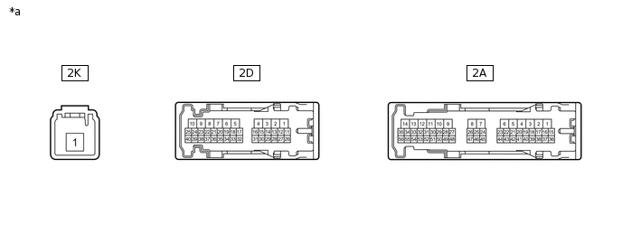
*a
Component without harness connected
(Main Body ECU)
-
-
Standard Resistance
Tester Connection
Condition
Specified Condition
2D-17 - 2K-1
Battery voltage not applied to terminals 2A-48 and 2D-4
10 kΩ or higher
Battery voltage applied to terminals 2A-48 and 2D-4
Below 1 Ω
If the result is not as specified, replace the main body ECU.
Inspect the IG1 No. 1 relay.
Measure the resistance according to the value(s) in the table below.

*a
Component without harness connected
(Main Body ECU)
-
-
Standard Resistance
Tester Connection
Condition
Specified Condition
2A-31 - 2K-1
Battery voltage not applied to terminals 2A-52 and 2D-4
10 kΩ or higher
Battery voltage applied to terminals 2A-52 and 2D-4
Below 1 Ω
If the result is not as specified, replace the main body ECU.