AIR CONDITIONING SYSTEM(for Automatic Air Conditioning System) Back-up Power Source Circuit
| DTC Code | DTC Name |
|---|---|
| Back-up Power Source Circuit |
DESCRIPTION
The back-up power source circuit for the air conditioning control assembly is shown below. Power is supplied even when the ignition switch is off. This power is used for diagnostic trouble code memory, etc.
WIRING DIAGRAM
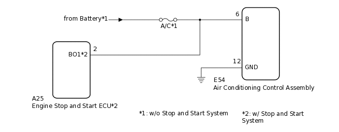
CAUTION / NOTICE / HINT
Inspect the fuses for circuits related to this system before performing the following procedure.
PROCEDURE
CONFIRM MODEL
Choose the model to be inspected.
Result
Result
Proceed to
w/o Stop and Start System
A
w/ Stop and Start System
B
B CHECK HARNESS AND CONNECTOR (AIR CONDITIONING CONTROL ASSEMBLY - ENGINE STOP AND START ECU)Click here
CHECK HARNESS AND CONNECTOR (AIR CONDITIONING CONTROL ASSEMBLY - POWER SOURCE)
Disconnect the E54 air conditioning control assembly connector.
Measure the voltage according to the value(s) in the table below.
Standard Voltage
Tester Connection
Condition
Specified Condition
E54-6 (B) - Body ground
Always
11 to 14 V
Result
Proceed to
OK
NG
NG REPAIR OR REPLACE HARNESS OR CONNECTOR
CHECK HARNESS AND CONNECTOR (AIR CONDITIONING CONTROL ASSEMBLY - BODY GROUND)
Measure the resistance according to the value(s) in the table below.
Standard Resistance
Tester Connection
Condition
Specified Condition
E54-12 (GND) - Body ground
Always
Below 1 Ω
Result
Proceed to
OK
NG
NG REPAIR OR REPLACE HARNESS OR CONNECTOR
CHECK HARNESS AND CONNECTOR (AIR CONDITIONING CONTROL ASSEMBLY - ENGINE STOP AND START ECU)
Disconnect the E54 air conditioning control assembly connector.
Disconnect the A25 engine stop and start ECU connector.
Measure the resistance according to the value(s) in the table below.
Standard Resistance
Tester Connection
Condition
Specified Condition
E54-6 (B) - A25-2 (BO1)
Always
Below 1 Ω
Result
Proceed to
OK
NG
NG REPAIR OR REPLACE HARNESS OR CONNECTOR
CHECK HARNESS AND CONNECTOR (AIR CONDITIONING CONTROL ASSEMBLY - POWER SOURCE)
Measure the resistance according to the value(s) in the table below.
Standard Resistance
Tester Connection
Condition
Specified Condition
E54-12 (GND) - Body ground
Always
Below 1 Ω
Reconnect the A25 engine stop and start ECU connector.
Measure the voltage according to the value(s) in the table below.
Standard Voltage
Tester Connection
Condition
Specified Condition
E54-6 (B) - E54-12 (GND)
Always
10 to 16 V
Result
Proceed to
OK
NG