RELAY ON-VEHICLE INSPECTION
-
INSPECT NO. 2 INTEGRATION RELAY (HD-LP NO. 1)
-
Check the HD-LP No. 1 relay.
-
Remove the H-LP RH-LO fuse.
-
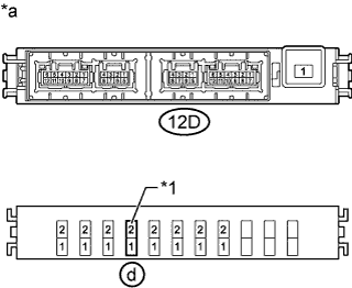
Text in Illustration *1 H-LP RH-LO Fuse *a Component without harness connected
(No. 2 Integration Relay)
Measure the resistance according to the value(s) in the table below.
Standard Resistance Tester Connection Condition Specified Condition d-2 - 12D-3 Battery voltage not applied to terminals d-2 and 12D-4 10 kΩ or higher Battery voltage applied to terminals d-2 and 12D-4 Below 1 Ω If the result is not as specified, replace the No. 2 integration relay.
-
Install the H-LP RH-LO fuse.
-
-
-
INSPECT NO. 2 INTEGRATION RELAY (DIM NO. 1)
-
Check the H-LP RH-HI fuse.
-
Measure the resistance according to the value(s) in the table below.
Standard Resistance Tester Connection Condition Specified Condition H-LP RH-HI fuse Always Below 1 Ω If the result is not as specified, replace the H-LP RH-HI fuse.
-
-
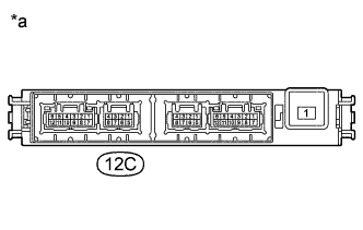
Check the DIM No. 1 relay.
-
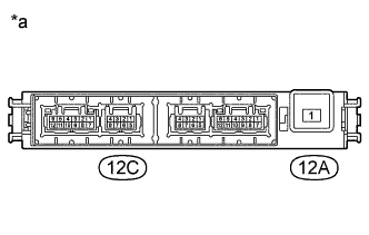
Text in Illustration *a Component without harness connected
(No. 2 Integration Relay)
Measure the resistance according to the value(s) in the table below.
Standard Resistance Tester Connection Condition Specified Condition 12A-1 - 12C-2 Battery voltage not applied to terminals 12C-3 and 12C-1 10 kΩ or higher Battery voltage applied to terminals 12C-3 and 12C-1 Below 1 Ω If the result is not as specified, replace the No. 2 integration relay.
-
-
-
INSPECT NO. 2 INTEGRATION RELAY (HD-LP NO. 2)
-
Check the HD-LP No. 2 relay.
-
Remove the H-LP LH-LO fuse.
-
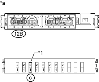
Text in Illustration *1 H-LP LH-LO Fuse *a Component without harness connected
(No. 2 Integration Relay)
Measure the resistance according to the value(s) in the table below.
Standard Resistance Tester Connection Condition Specified Condition c-2 - 12B-9 Battery voltage not applied to terminals c-2 and 12B-10 10 kΩ or higher Battery voltage applied to terminals c-2 and 12B-10 Below 1 Ω If the result is not as specified, replace the No. 2 integration relay.
-
Install the H-LP LH-LO fuse.
-
-
-
INSPECT NO. 2 INTEGRATION RELAY (DIM NO. 2)
-
Check the H-LP LH-HI fuse.
-
Measure the resistance according to the value(s) in the table below.
Standard Resistance Tester Connection Condition Specified Condition H-LP LH-HI fuse Always Below 1 Ω If the result is not as specified, replace the H-LP LH-HI fuse.
-
-
Check the DIM No. 2 relay.
-
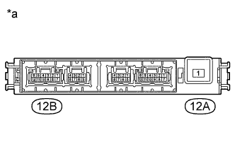
Text in Illustration *a Component without harness connected
(No. 2 Integration Relay)
Measure the resistance according to the value(s) in the table below.
Standard Resistance Tester Connection Condition Specified Condition 12A-1 - 12B-12 Battery voltage not applied to terminals 12B-8 and 12B-11 10 kΩ or higher Battery voltage applied to terminals 12B-8 and 12B-11 Below 1 Ω If the result is not as specified, replace the No. 2 integration relay.
-
-
-
INSPECT NO. 2 INTEGRATION RELAY (IG2)
-
Check the IG2-MAIN fuse.
-
Measure the resistance according to the value(s) in the table below.
Standard Resistance Tester Connection Condition Specified Condition IG2-MAIN fuse Always Below 1 Ω If the result is not as specified, replace the IG2-MAIN fuse.
-
-
Check the IG2 relay.
-
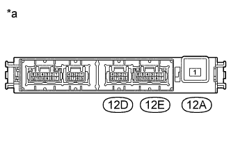
Text in Illustration *a Component without harness connected
(No. 2 Integration Relay)
Measure the resistance according to the value(s) in the table below.
Standard Resistance Tester Connection Condition Specified Condition 12A-1 - 12D-1 Battery voltage not applied to terminals 12D-2 and 12E-4 10 kΩ or higher Battery voltage applied to terminals 12D-2 and 12E-4 Below 1 Ω If the result is not as specified, replace the No. 2 integration relay.
-
-
-
INSPECT NO. 2 INTEGRATION RELAY (DRL)
-
Check the DRL fuse.
-
Measure the resistance according to the value(s) in the table below.
Standard Resistance Tester Connection Condition Specified Condition DRL fuse Always Below 1 Ω If the result is not as specified, replace the DRL fuse.
-
-
Check the DRL relay.
-
Text in Illustration *a Component without harness connected
(No. 2 Integration Relay)
Measure the resistance according to the value(s) in the table below.
Standard Resistance Tester Connection Condition Specified Condition 12A-1 - 12D-6 Battery voltage not applied to terminals 12E-12 and 12D-7 10 kΩ or higher Battery voltage applied to terminals 12E-12 and 12D-7 Below 1 Ω If the result is not as specified, replace the No. 2 integration relay.
-
-
-
INSPECT NO. 2 INTEGRATION RELAY (ACC)
-
Check the ACC relay.
-
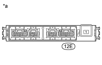
Text in Illustration *a Component without harness connected
(No. 2 Integration Relay)
Measure the resistance according to the value(s) in the table below.
Standard Resistance Tester Connection Condition Specified Condition 12E-7 - 12E-9 Battery voltage not applied to terminals 12E-8 and 12E-4 10 kΩ or higher Battery voltage applied to terminals 12E-8 and 12E-4 Below 1 Ω If the result is not as specified, replace the No. 2 integration relay.
-
-
-
INSPECT NO. 2 INTEGRATION RELAY (100V)
-
Check the 100V fuse.
-
Measure the resistance according to the value(s) in the table below.
Standard Resistance Tester Connection Condition Specified Condition 100V fuse Always Below 1 Ω If the result is not as specified, replace the 100V fuse.
-
-
Check the 100V relay.
-
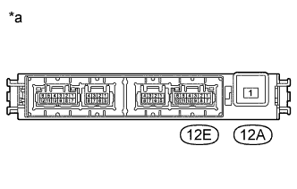
Text in Illustration *a Component without harness connected
(No. 2 Integration Relay)
Measure the resistance according to the value(s) in the table below.
Standard Resistance Tester Connection Condition Specified Condition 12A-1 - 12E-3 Battery voltage not applied to terminals 12E-1 and 12E-4 10 kΩ or higher Battery voltage applied to terminals 12E-1 and 12E-4 Below 1 Ω If the result is not as specified, replace the No. 2 integration relay.
-
-
-
INSPECT NO. 2 INTEGRATION RELAY (FR FOG)
-
Check the FR FOG relay.
-
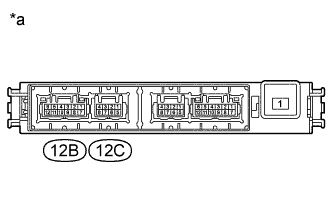
Text in Illustration *a Component without harness connected
(No. 2 Integration Relay)
Measure the resistance according to the value(s) in the table below.
Standard Resistance Tester Connection Condition Specified Condition 12B-3 - 12B-1 Battery voltage not applied to terminals 12B-6 and 12C-4 10 kΩ or higher Battery voltage applied to terminals 12B-6 and 12C-4 Below 1 Ω If the result is not as specified, replace the No. 2 integration relay.
-
-
-
INSPECT NO. 2 INTEGRATION RELAY (DOME CUT)
-
Check the DOME CUT relay.
-
Text in Illustration *a Component without harness connected
(No. 2 Integration Relay)
Measure the resistance according to the value(s) in the table below.
Standard Resistance Tester Connection Condition Specified Condition 12C-7 - 12C-6 Battery voltage not applied to terminals 12C-8 and 12C-5 10 kΩ or higher Battery voltage applied to terminals 12C-8 and 12C-5 Below 1 Ω If the result is not as specified, replace the No. 2 integration relay.
-
-