INTAKE MANIFOLD INSTALLATION
PROCEDURE
INSTALL STUD BOLT
Tip:If a stud bolt is deformed or the threads are damaged, replace it.
Using an E6 "TORX" socket wrench, install the 2 stud bolts to the intake manifold.
5.0 N*m
51 kgf*cm
44 in.*lbf
INSTALL NO. 1 INTAKE MANIFOLD TO HEAD GASKET
Install a new No. 1 intake manifold to head gasket to the intake manifold.
INSTALL INTAKE MANIFOLD
for LHD:
Install the hose clamp to the intake manifold.
for RHD:
Install the 2 hose clamps to the intake manifold.
Temporarily install the intake manifold to the cylinder head sub-assembly with the 4 bolts.
-
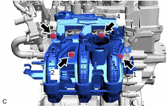
Tighten the 4 bolts in the order shown in the illustration.
24 N*m
245 kgf*cm
18 ft.*lbf
-
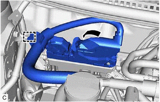
for LHD:
Connect the ECM connector and lower the lever.
Note:When connecting the ECM connector, make sure that dirt, water or other foreign matter does not contact the connecting parts of the ECM connector.
Be sure to securely connect the ECM connector.
Engage the wire harness clamp.
CONNECT ENGINE WIRE
-

Engage the 2 wire harness clamps.
-

Engage the 3 wire harness clamps and connect the engine wire to the intake manifold.
Connect the wire harness clamp bracket to the intake manifold with the bolt.
8.4 N*m
86 kgf*cm
74 in.*lbf
-
INSTALL CLUTCH CABLE BRACKET (for Manual Transaxle)
Install the clutch cable bracket with the 2 nuts.
5.5 N*m
56 kgf*cm
49 in.*lbf
INSTALL FUEL HOSE BRACKET
Install the fuel hose bracket to the intake manifold with the bolt.
8.0 N*m
82 kgf*cm
71 in.*lbf
Engage the fuel tube sub-assembly to the hose clamp.
CONNECT VACUUM HOSE ASSEMBLY
for LHD:
Engage the vacuum hose assembly to the hose clamp.
for RHD:
Engage the vacuum hose assembly to the 2 hose clamps.
Align the vacuum hose assembly connector with the intake manifold, and push them together until the vacuum hose assembly connector makes a "click" sound.
CONNECT NO. 2 FUEL VAPOR FEED HOSE
Connect the No. 2 fuel vapor feed hose to the intake manifold and slide the clip to secure it.
ENGAGE WATER BY-PASS HOSE ASSEMBLY
Engage the water by-pass hose assembly to the 4 hose clamps.
INSTALL NO. 1 EGR PIPE SUB-ASSEMBLY
Install 2 new EGR pipe gaskets to the No. 1 EGR pipe sub-assembly and intake manifold.
-
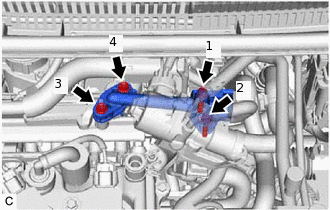
Temporarily install the No. 1 EGR pipe sub-assembly with the 2 bolts and 2 nuts.
Tighten the 2 bolts and 2 nuts in the order shown in the illustration.
10 N*m
102 kgf*cm
7 ft.*lbf
INSTALL PURGE VALVE (PURGE VSV)
INSTALL THROTTLE BODY WITH MOTOR ASSEMBLY
INSTALL OUTER COWL TOP PANEL (for LHD)
INSTALL OUTER COWL TOP PANEL (for RHD)
INSTALL FRONT AIR SHUTTER SEAL RH (for LHD)
INSTALL FRONT AIR SHUTTER SEAL RH (for RHD)
INSTALL FRONT NO. 1 VENTILATOR SEAL (for LHD)
INSTALL FRONT NO. 1 VENTILATOR SEAL (for RHD)
INSTALL WINDSHIELD WIPER MOTOR AND LINK ASSEMBLY