REAR AXLE BEAM REMOVAL

CAUTION / NOTICE / HINT
Note
When the brake pedal is first depressed after replacing the brake pads or pushing back the disc brake piston, DTC C1214 may be output. As there is no malfunction, clear the DTC.
PROCEDURE
-
PRECAUTION
Note
After turning the power switch off, waiting time may be required before disconnecting the cable from the negative (-) auxiliary battery terminal. Therefore, make sure to read the disconnecting the cable from the negative (-) auxiliary battery terminal notices before proceeding with work Click here.
-
DISABLE BRAKE CONTROL
-
REMOVE REAR WHEELS
-
DRAIN BRAKE FLUID
Note
If brake fluid leaks onto any painted surface, immediately wash it off.
-
REMOVE REAR FLOOR SIDE MEMBER COVER RH
-
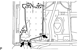
Remove the 3 bolts.
-
Disengage the 3 clips and remove the rear floor side member cover RH.
-
-
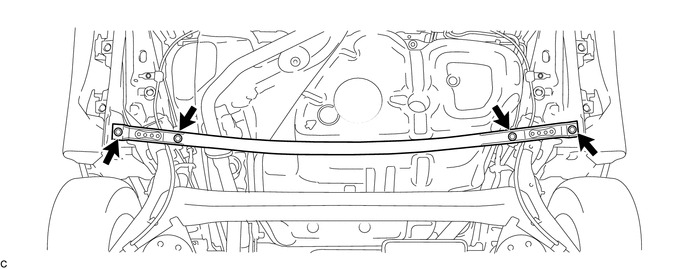
REMOVE REAR SUSPENSION BRACE SUB-ASSEMBLY
-
Remove the 4 bolts and the rear suspension brace sub-assembly.
-
-
DISCONNECT SKID CONTROL SENSOR WIRE LH
-
DISCONNECT SKID CONTROL SENSOR WIRE RH
Tech Tips
Perform the same procedure as for the LH side.
-
SEPARATE SKID CONTROL SENSOR WIRE LH
-
SEPARATE SKID CONTROL SENSOR WIRE RH
Tech Tips
Perform the same procedure as for the LH side.
-
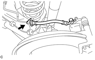
SEPARATE REAR BRAKE TUBE FLEXIBLE HOSE (for LH Side)
-
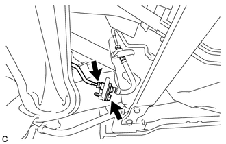
Using a union nut wrench, separate the rear brake tube flexible hose from the No. 4 brake tube.
Note
-
Do not bend or damage the brake line.
-
Do not allow any foreign matter such as dirt or dust to enter the brake line from the connecting points.
-
-
Remove the bolt and separate the rear brake tube flexible hose from the rear axle beam assembly.
-
-
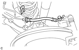
SEPARATE REAR BRAKE TUBE FLEXIBLE HOSE (for RH Side)
-
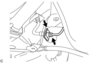
Using a union nut wrench, separate the rear brake tube flexible hose from the No. 3 brake tube.
Note
-
Do not bend or damage the brake line.
-
Do not allow any foreign matter such as dirt or dust to enter the brake line from the connecting points.
-
-
Remove the clip and separate the rear brake tube flexible hose from the rear axle beam assembly.
-
-
REMOVE REAR DISC BRAKE CALIPER ASSEMBLY LH
-
Using a union nut wrench, separate the No. 4 brake tube while holding the rear flexible hose LH with a wrench.
Note
-
Do not bend or damage the brake line.
-
Do not allow any foreign matter such as dirt or dust to enter the brake line from the connecting points.
-
-
Remove the clip and separate the rear flexible hose LH.
-
Remove the 2 bolts and rear disc brake caliper assembly LH with rear flexible hose LH.
-
-
REMOVE REAR DISC BRAKE CALIPER ASSEMBLY RH
Tech Tips
Perform the same procedure as for the LH side.
-
REMOVE PARKING BRAKE SHOE ADJUSTING HOLE PLUG
-
Remove the 2 parking brake shoe adjusting hole plugs.
-
-
REMOVE REAR DISC (for LH Side)
-
REMOVE REAR DISC (for RH Side)
Tech Tips
Perform the same procedure as for the LH side.
-
REMOVE REAR NO. 4 BRAKE TUBE
-
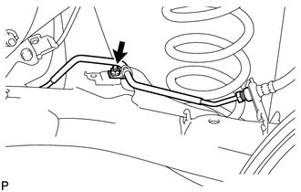
Remove the nut and rear No. 4 brake tube from the rear axle beam assembly.
-
-
REMOVE REAR NO. 3 BRAKE TUBE
Tech Tips
Perform the same procedure as for the rear No. 4 brake tube.
-
REMOVE REAR AXLE HUB AND BEARING ASSEMBLY LH
-
REMOVE REAR AXLE HUB AND BEARING ASSEMBLY RH
Tech Tips
Perform the same procedure as for the LH side.
-
SEPARATE PARKING BRAKE ASSEMBLY (for LH Side)
-
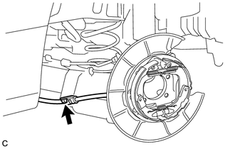
Remove the bolt and separate the No. 3 parking brake cable assembly from the rear axle beam assembly.
-
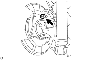
Remove the nut and separate the parking brake assembly from the rear axle beam assembly.
Note
Use wire or an equivalent tool to keep the parking brake assembly from hanging down by the parking brake cable.
-
-
SEPARATE PARKING BRAKE ASSEMBLY (for RH Side)
Tech Tips
Perform the same procedure as for the LH side.
-
SEPARATE REAR WHEEL HOUSE LINER LH
-
SEPARATE REAR WHEEL HOUSE LINER RH
Tech Tips
Perform the same procedure as for the LH side.
-
SEPARATE REAR HEIGHT CONTROL SENSOR SUB-ASSEMBLY (w/ Height Control Sensor)
-
REMOVE REAR COIL SPRING LH
-
REMOVE REAR COIL SPRING RH
Tech Tips
Perform the same procedure as for the LH side.
-
REMOVE REAR UPPER COIL SPRING INSULATOR LH
-
REMOVE REAR UPPER COIL SPRING INSULATOR RH
-
REMOVE REAR LOWER COIL SPRING INSULATOR LH
-
REMOVE REAR LOWER COIL SPRING INSULATOR RH
-
REMOVE REAR AXLE BEAM ASSEMBLY
-
Support the rear axle beam assembly with an engine lifter using 2 wooden blocks and 2 attachments or equivalent tools to replicate standard vehicle height conditions as shown in the illustration.
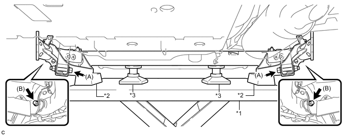
Text in Illustration *1 Engine Lifter *2 Wooden Block *3 Attachment - - Note
Make sure to secure the rear axle beam assembly to prevent it from dropping.
-
Remove the 2 bolts (A) and 2 nuts while holding the 2 nuts and separate the rear axle beam assembly from the rear shock absorber assemblies LH and RH.
Note
Since the stopper nuts are used, turn the bolts.
-
Remove the 2 bolts (B) and rear axle beam assembly.
-
-
REMOVE REAR AXLE CARRIER BUSHING LH
-
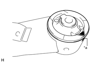
Text in Illustration *a Matchmark Put a matchmark on the rear axle beam assembly so that the mark aligns with the arrow mark on the rear axle carrier bushing LH. (If the rear axle beam assembly is reused.)
-
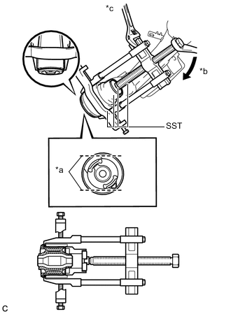
Text in Illustration *a Bend Portion *b Turn *c Hold Using a chisel and hammer, bend the 2 ribs on the rear axle carrier bushing LH.
Note
When removing the rear axle carrier bushing, do not erase the matchmark on the rear axle beam assembly.
-
Using SST, remove the rear axle carrier bushing LH from the rear axle beam assembly.
- SST
- 09710-26011 ( 09710-05061 )
- 09950-40011 ( 09951-04020, 09952-04010, 09953-04030, 09954-04020, 09955-04051, 09957-04010, 09958-04011 )
- 09950-60010 ( 09951-00530 )
Note
Apply grease to the threads and tip of the SST center bolt before use.
-
-
REMOVE REAR AXLE CARRIER BUSHING RH
Tech Tips
Perform the same procedure as for the LH side.