CYLINDER HEAD (w/ Dual VVT-i) REMOVAL
-
REMOVE MANUAL TRANSMISSION ASSEMBLY (for Manual Transmission)
-
REMOVE AUTOMATIC TRANSMISSION ASSEMBLY (for Automatic Transmission)
-
REMOVE CHAIN SUB-ASSEMBLY
-
REMOVE CAMSHAFT BEARING CAP
-
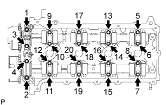
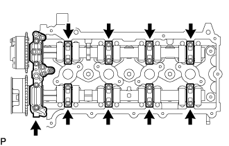
Uniformly loosen and remove the 20 bearing cap bolts in the sequence shown in the illustration.
Note
Uniformly loosen the bolts while keeping the camshafts level.
-
Remove the 9 bearing caps.
Tech Tips
Arrange the removed parts in the correct order.
-
-
REMOVE CAMSHAFT
-
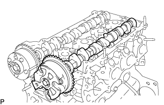
Remove the camshaft.
-
-
REMOVE NO. 2 CAMSHAFT
-
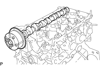
Remove the No. 2 camshaft.
-
-
REMOVE NO. 1 VALVE ROCKER ARM SUB-ASSEMBLY
-
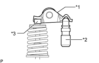
Text in Illustration *1 No. 1 Valve Rocker Arm Sub-assembly *2 Valve Lash Adjuster Assembly *3 Valve Stem Cap Remove the 16 No. 1 valve rocker arm sub-assemblies from the cylinder head sub-assembly.
Tech Tips
Arrange the removed parts in the correct order.
-
-
REMOVE VALVE LASH ADJUSTER ASSEMBLY
-
Remove the 16 valve lash adjuster assemblies from the cylinder head sub-assembly.
Tech Tips
Arrange the removed parts in the correct order.
-
-
REMOVE VALVE STEM CAP
-
Remove the 16 valve stem caps from the cylinder head sub-assembly.
Tech Tips
Arrange the removed parts in the correct order.
-
-
REMOVE CYLINDER HEAD SUB-ASSEMBLY
-
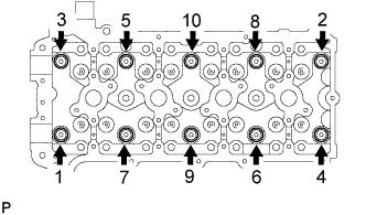
Uniformly loosen the 10 bolts in the sequence shown in the illustration. Remove the 10 cylinder head bolts and plate washers.
Note
-
Be careful not to drop plate washers into the cylinder head sub-assembly.
-
Head warpage or cracking could result from removing bolts in the incorrect order.
-
-
Remove the cylinder head sub-assembly.
-
-
REMOVE CYLINDER HEAD GASKET
-
INSPECT CYLINDER HEAD SET BOLT
-
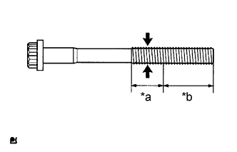
Text in Illustration *a Measuring area *b Distance Using a vernier caliper, measure the diameter of the most elongated threads in the measuring area.
Standard outside diameter 10.76 to 10.97 mm (0.424 to 0.432 in.) Minimum outside diameter 10.40 mm (0.409 in.) Distance 30 mm (1.18 in.) If a visual check reveals no excessively thin areas, check the center of the measuring area (see illustration) and find the area that has the smallest diameter.
If the diameter is less than the minimum, replace the cylinder head set bolt.
-
-
INSPECT CYLINDER HEAD SUB-ASSEMBLY
-
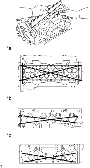
Text in Illustration *a Cylinder Block Side *b Intake Manifold Side *c Exhaust Manifold Side Using a precision straightedge and feeler gauge, measure the warpage of the contact surface of the cylinder block and manifolds.
Maximum warpage 0.05 mm (0.00197 in.) If the warpage is more than the maximum, replace the cylinder head sub-assembly.
-
Using a dye penetrant, check the intake ports, exhaust ports and cylinder surface for cracks.
If cracked, replace the cylinder head sub-assembly.
-