MANUAL TRANSMISSION ASSEMBLY INSTALLATION
PROCEDURE
-
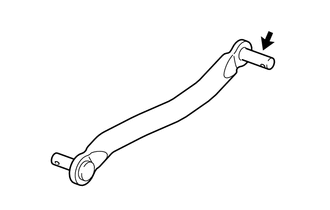
INSTALL CONTROL SHAFT
-
INSTALL FLOOR SHIFT CONTROL SHAFT
-
INSTALL REAR NO. 1 ENGINE MOUNTING INSULATOR
-
Install the rear No. 1 engine mounting insulator to the manual transmission assembly with the 4 bolts.
- Torque:
- 40 N*m { 408 kgf*cm, 30 ft.*lbf }
-
-
INSTALL MANUAL TRANSMISSION ASSEMBLY
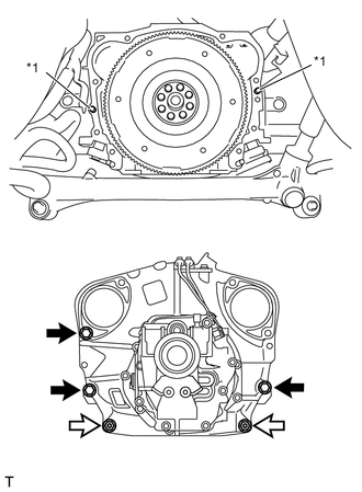
Text in Illustration *1 Knock Pin 
Bolt 
Nut
-
Confirm that 2 knock pins are on the manual transmission assembly contact surface of the engine cylinder block before manual transmission assembly installation.
-
Install the manual transmission assembly to the engine with the 3 bolts and 2 nuts.
- Torque:
- 50 N*m { 510 kgf*cm, 37 ft.*lbf }
Note
-
Do not apply excessive force to the transmission assembly as this will break the input shaft.
-
Insert dowel pins into the dowel holes securely so that the end face of the transmission assembly fits close against the engine assembly before tightening the bolts.
-
-
INSTALL FLOOR SHIFT CONTROL SHIFT LEVER RETAINER
-
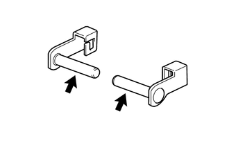
Apply a light coat of MP grease to new 2 shift lever pins.
Text in Illustration MP grease -
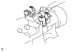
Install the floor shift control shift lever retainer with the 2 shift lever pins.
-
Secure the shift lever pins to the extension housing sub-assembly.
-
-
INSTALL REAR NO. 2 ENGINE MOUNTING INSULATOR
-
Tilt up the manual transmission assembly.
-
Install the rear No. 2 engine mounting insulator to the rear No. 1 engine mounting insulator with 2 washers and 2 nuts.
- Torque:
- 55 N*m { 561 kgf*cm, 41 ft.*lbf }
-
Install the rear No. 2 engine mounting insulator to the body with the 4 bolts.
- Torque:
- 65 N*m { 663 kgf*cm, 48 ft.*lbf }
-
-
INSTALL EXHAUST PIPE BRACKET
-
Install the exhaust pipe bracket with the 2 bolts.
- Torque:
- 23 N*m { 235 kgf*cm, 17 ft.*lbf }
-
-
INSTALL SHIFT AND SELECT LEVER BOOT
-
Temporarily install a new shift and select lever boot to the floor shift lever assembly.
-
-
INSTALL FLOOR SHIFT LEVER ASSEMBLY
-
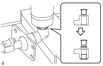
While holding the collar with your hand, press the collar slowly straight into the floor shift lever assembly hole using a press.
Note
Be careful that your hand does not get caught.
-
Install the O-ring to the floor shift lever assembly.
-
While holding the collar with your hand, press the collar slowly straight into the floor shift lever assembly hole using a press.
Note
Be careful that your hand does not get caught.
-
Apply a light coat of MP grease to the floor shift control shaft.
Text in Illustration MP grease -
Install the plate washer to the floor shift lever assembly.
-
Install the shift lever assembly with the clip.
-
Install the shift and select lever boot.
Note
Do not damage the shift and select lever boot.
-
-
INSTALL EXHAUST MANIFOLD
-
INSTALL MANUAL TRANSMISSION ASSEMBLY
-
Install the bolt to the manual transmission assembly.
- Torque:
- 50 N*m { 510 kgf*cm, 37 ft.*lbf }
-
-
INSTALL CLUTCH RELEASE CYLINDER ASSEMBLY
-
Install the clutch release cylinder assembly with the 2 bolts.
- Torque:
- 37 N*m { 377 kgf*cm, 27 ft.*lbf }
-
-
CONNECT WIRE HARNESS
-
Install the wire harness clamp bracket with the bolt.
- Torque:
- 10 N*m { 102 kgf*cm, 7 ft.*lbf }
-
Engage the wire harness clamp.
-
Connect the ground cable with the bolt.
- Torque:
- 13 N*m { 133 kgf*cm, 10 ft.*lbf }
-
Connect the 2 connectors.
-
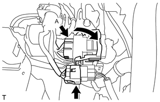
Connect the 2 connectors.
Tech Tips
Press down the lever until the claw of the connector A makes a connection sound.
-
-
INSTALL STARTER ASSEMBLY
-
INSTALL FRONT STABILIZER BAR
-
INSTALL PROPELLER SHAFT WITH CENTER BEARING ASSEMBLY
-
CONNECT CABLE TO NEGATIVE BATTERY TERMINAL
-
ADD MANUAL TRANSMISSION OIL
-
INSPECT MANUAL TRANSMISSION OIL
-
INSPECT FOR MANUAL TRANSMISSION OIL LEAK
-
INSTALL REAR ENGINE UNDER COVER LH (w/ Floor Under Cover)
-
INSTALL REAR ENGINE UNDER COVER RH (w/ Floor Under Cover)
Tech Tips
Use the same procedure for the RH side as for the LH side.
-
INSTALL NO. 2 ENGINE UNDER COVER
-
INSTALL NO. 1 ENGINE UNDER COVER