CAMSHAFT REMOVAL
CAUTION / NOTICE / HINT
After the engine has stopped, wait at least 1 minute before releasing the high pressure lines.
When working on the fuel circuit, protect the generator assembly against dirt contamination.
Cover the generator assembly with suitable materials.
Failure to comply with this procedure may result in a generator assembly malfunction.
-
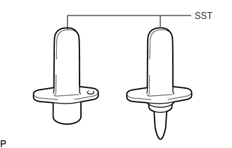
After disconnecting the pressure line, it is absolutely essential to seal the injector assemblies and the common rail assembly with SST.
SST
PZ4TB-04941-79
PROCEDURE
PRECAUTION
Note:After turning the ignition switch off, waiting time may be required before disconnecting the cable from the battery terminal. Therefore, make sure to read the disconnecting the cable from the battery terminal notice before proceeding with work (Click here).
DISCONNECT CABLE FROM NEGATIVE BATTERY TERMINAL
Note:When disconnecting the cable, some systems need to be initialized after the cable is reconnected (Click here).
REMOVE RADIATOR ASSEMBLY
REMOVE DIESEL THROTTLE BODY ASSEMBLY
REMOVE ENGINE COVER
REMOVE AIR CLEANER CAP SUB-ASSEMBLY WITH AIR CLEANER HOSE ASSEMBLY
REMOVE AIR CLEANER FILTER ELEMENT SUB-ASSEMBLY
REMOVE AIR CLEANER CASE SUB-ASSEMBLY
DISCONNECT ENGINE WIRE
REMOVE ENGINE OIL LEVEL DIPSTICK GUIDE
DISCONNECT NO. 2 VACUUM HOSE ASSEMBLY
REMOVE NO. 1 VACUUM PIPE
REMOVE INTAKE MANIFOLD
REMOVE NO. 3 INJECTION PIPE SUB-ASSEMBLY
REMOVE INJECTION PIPE SUB-ASSEMBLY
REMOVE COMMON RAIL ASSEMBLY
REMOVE CAMSHAFT POSITION SENSOR
REMOVE NOZZLE LEAKAGE PIPE ASSEMBLY
REMOVE INJECTOR ASSEMBLY
SET NO. 1 CYLINDER TO TDC/COMPRESSION
-
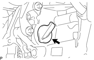
Remove the plug from the cylinder block.
-
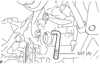
Set SST (A) to the plug hole of the cylinder block.
SST(A)
PZ4TB-04951-26
-
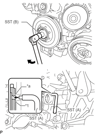
Using SST (B), turn the crankshaft pulley clockwise until SST(A) fits into the groove of the flywheel with damper assembly.
SST (B)
PZ4TB-04933-80
Table 1. Text in Illustration *1
Flywheel with Damper Assembly
*a
Groove
Using SST(A), hold the flywheel with damper assembly.
SST (A)
PZ4TB-04951-26
Remove SST.
Install the plug to the cylinder block.
-
REMOVE OIL FILLER CAP SUB-ASSEMBLY
REMOVE VACUUM CONTROL VALVE BRACKET
REMOVE CYLINDER HEAD COVER SUB-ASSEMBLY
-
Using an E10 "TORX" socket wrench, loosen the 17 bolts and remove the cylinder head cover sub-assembly.
Tip:Bolt cannot be removed from the cylinder head cover sub-assembly.
-
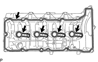
Remove the 5 gaskets from the cylinder head cover sub-assembly.
-
HOLDING CAMSHAFT AND NO. 2 CAMSHAFT
-
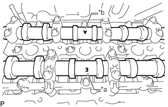
Check that the camshaft and No. 2 camshaft on the camshaft housing sub-assembly as shown in the illustration so that mark E and mark A face upward.
Table 2. Text in Illustration *a
Mark E (Intake Side)
*b
Mark A (Exhaust Side)
Note:If the marks of the camshaft and No. 2 camshaft are not at the positions shown in the illustration, perform set No. 1 cylinder to TDC again.
-
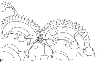
Check the camshaft and No. 2 camshaft timing marks.
Table 3. Text in Illustration *a
Timing Mark
-
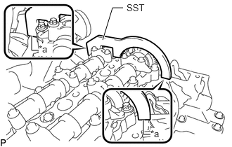
Set SST and secure the camshaft and No. 2 camshaft.
SST
PZ4TB-04961-12
Table 4. Text in Illustration *a
No Clearance
Note:Make sure there is no clearance between SST and the camshaft housing sub-assembly.
-
REMOVE NO. 1 TURBO INSULATOR
REMOVE NO. 1 EXHAUST MANIFOLD HEAT INSULATOR
REMOVE NO. 2 CHAIN TENSIONER ASSEMBLY
-
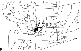
Using a 24 mm socket wrench, remove the No. 2 chain tensioner assembly.
-
REMOVE NO. 2 ENGINE HANGER
REMOVE NO. 2 TIMING CHAIN GUIDE
-
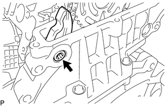
Using a T45 "TORX" socket wrench, remove the bolt and No. 2 timing chain guide.
-
REMOVE CAMSHAFT AND NO. 2 CAMSHAFT
-
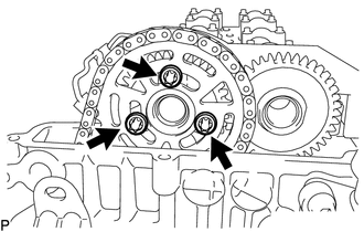
Using an E10 "TORX" socket wrench, remove the 3 bolts and the camshaft timing sprocket.
Note:Do not drop the No. 2 chain sub-assembly into the gap between the cylinder block and timing chain cover plate.
-
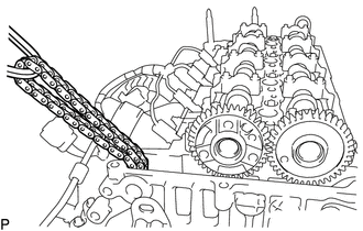
Suspend the No. 2 chain sub-assembly with a string or equivalent.
Remove SST securing the camshaft and No. 2 camshaft.
-
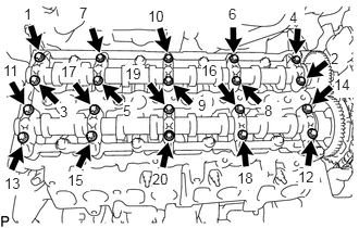
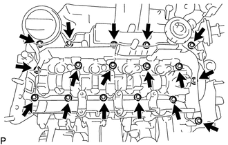
Using an E8 "TORX" socket wrench, uniformly loosen the 20 bolts 180° in several steps in the sequence shown in the illustration.
Uniformly loosen the 20 bolts further in several steps in the sequence shown in the illustration and remove the bolts.
Remove the 5 intake camshaft bearing caps and 5 exhaust camshaft bearing caps.
Tip:Arrange the removed parts in the correct order.
Remove the camshaft and No. 2 camshaft.
-
REMOVE CAMSHAFT HOUSING SUB-ASSEMBLY
-
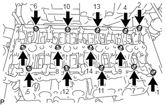
Using an E10 "TORX" socket wrench, remove the 14 bolts and camshaft housing sub-assembly.
-
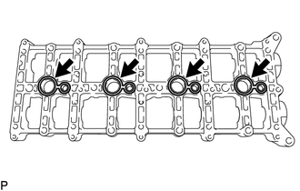
Remove the 4 gaskets.
-
REMOVE NO. 1 VALVE ROCKER ARM SUB-ASSEMBLY
Remove the 16 No. 1 valve rocker arm sub-assemblies.
Tip:Arrange the removed parts in the correct order.
REMOVE VALVE LASH ADJUSTER ASSEMBLY
Remove the 16 valve lash adjuster assemblies from the cylinder head sub-assembly.
Tip:Arrange the removed parts in the correct order.