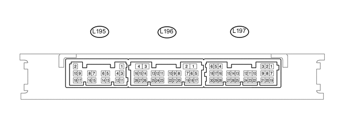
ENTRY AND START SYSTEM(for Start Function) TERMINALS OF ECU
-
CHECK CERTIFICATION ECU (SMART KEY ECU ASSEMBLY)
-
Disconnect the 195 and L197 certification ECU (smart key ECU assembly) connectors.
-
Measure the voltage and resistance according to the value(s) in the table below.
Tech Tips
Measure the values on the wire harness side with the connector disconnected.
Terminal No. (Symbol) Input/Output Wiring Color Terminal Description Condition Specified Condition Related Data List Item 195-9 (IG2D) - Body ground Output V - Body ground IG2 signal 20°C (68°F) Approximately 310.14 Ω IG2 Relay Monitor(Outsid e) 195-18 (STP1) - Body ground Input G - Body ground Stop light switch signal Brake pedal depressed → Brake pedal released 9 V or higher → 1 V or less Stop Light Switch1 195-2 (+B) - Body ground Input B - Body ground Power source Power switch off 11 to 14 V - 195-11 (E) - Body ground - W-B - Body ground Ground Always Below 1 Ω - L197-30 (SSW2) - Body ground Input B - Body ground SSW2 contact signal
Tech Tips
Backup for SSW1. Behaves the same way as SSW1.
Power switch pushed → Power switch not pushed Below 1 Ω → 10 kΩ or higher Start Switch2 L197-28 (SSW1) - Body ground Input W - Body ground SSW1 contact signal Power switch pushed → Power switch not pushed Below 1 Ω → 10 kΩ or higher Start Switch1 L197-6 (IG1D) - Body ground Output B - Body ground IG1 signal 20°C (68°F) 54.32 to 79.32 Ω IG1 Relay Monitor(Outsid e) L197-4 (ACCD) - Body ground Output G - Body ground ACC signal 20°C (68°F) 163 to 238 Ω ACC Relay Monitor L197-27 (SPD) - 195-11 (E) Input V - W-B Vehicle speed signal Always 30 kΩ or higher Vehicle Speed Signal L197-25 (PPOS) - Body ground Input LG - Body ground P position signal Always 30 kΩ or higher - -
Reconnect the 195 and L197 certification ECU (smart key ECU assembly) connectors.
-
Measure the voltage and check for pulses according to the value(s) in the table below.
Terminal No. (Symbol) Input/Output Wiring Color Terminal Description Condition Specified Condition Related Data List Item 195-9 (IG2D) - 195-11 (E) Output V - W-B IG2 signal Power switch on (ACC) → Power switch on (IG) 1 V or less → 9 V or higher - L197-30 (SSW2) - 195-11 (E) Input B - W-B SSW2 contact signal
Tech Tips
Backup for SSW1. Behaves the same way as SSW1.
Power switch not pushed → Power switch pushed 9 V or higher → 1 V or less Start Switch2 L197-28 (SSW1) - 195-11 (E) Input W - W-B SSW1 contact signal Power switch not pushed → Power switch pushed 9 V or higher → 1 V or less Start Switch1 L197-4 (ACCD) - 195-11 (E) Output G - W-B ACC signal Power switch off → Power switch on (ACC) 1 V or less → 8.5 V or highern ACC Relay Monitor L197-6 (IG1D) - 195-11 (E) Output B - W-B IG1 signal) Power switch on (ACC) → Power switch on (IG) 1 V or less → 9 V or higher IG1 Relay Monitor(Outsid e) 195-7 (ST2) - Body ground Output G - Body ground Starting control signal
-
P position signal
-
With the brake pedal depresse d, the power switch is pressed and held → After approx. 3 sec. has elapsed, the power switch is released
9 V or higher → 1 V or less - L197-27 (SPD) - 195-11 (E) Input V - W-B Vehicle speed signal Vehicle being driven at approx. 5 km/h (3 mph) Pulse generation (See waveform 2) Vehicle Speed Signal L197-25 (PPOS) - 195-11 (E) Input LG - W-B P position signal
-
P position signal
-
Power switch on (ACC) → Power switch on (IG)
Pulse generation (See waveform 1) - -
-
Using an oscilloscope, check the waveform of the ECU.
-
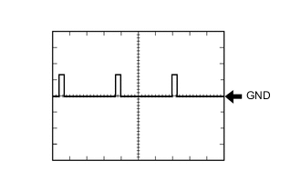
Waveform 1
Item Content Tester Connection L197-25 (PPOS) - 195-11 (E) Tool Setting 10 V/DIV., 10 ms/DIV. Condition Power switch on (IG), P position -
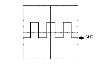
Waveform 2
Item Content Tester Connection L197-27 (SPD) - 195-11 (E) Tool Setting 5 V/DIV., 100 ms./DIV. Condition Power switch on (READY), vehicle being driven at approx. 5 km/h (3 mph) Tech Tips
The wavelength becomes shorter as the vehicle speed increases.
-
-