MANIFOLD ABSOLUTE PRESSURE SENSOR ON-VEHICLE INSPECTION
PROCEDURE
-
INSPECT NO. 1 INSPECT TURBO PRESSURE SENSOR (w/ Canister Pump Module)
-
Remove the No. 1 turbo pressure sensor.
-
Connect the No. 1 turbo pressure sensor connector.
-
Connect the GTS to the DLC3.
-
Turn the engine switch on (IG).
-
Turn the GTS on.
-
Enter the following menus: Powertrain / Engine / Data List / Intake Manifold Absolute Pressure.
Powertrain > Engine > Data ListTester Display Intake Manifold Absolute Pressure -
According to the display on the GTS, read the Data List.
Tech Tips
-
Standard atmospheric pressure is approximately 101 kPa (abs) (15 psi (abs)).
-
For every 100 m (328 ft) increase in altitude, atmospheric pressure drops by approximately 1 kPa (0.15 psi). This varies by weather.
-
-

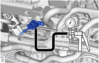
*1 No. 1 Turbo Pressure Sensor *a Hose with an inside diameter of 12 mm (0.472 in.) *b Hose Adapter Connect a vacuum pump to the No. 1 turbo pressure sensor as shown in the illustration.
-
Read the Data List while applying vacuum and pressure to the No. 1 turbo pressure sensor using the vacuum pump.
OK The values indicated on the vacuum pump when applying vacuum and pressure and the Data List are nearly the same. Note
-
Do not apply a pressure of 50 kPa (0.5 kgf/cm2, 7.3 psi) or more to the No. 1 turbo pressure sensor.
-
Do not apply a vacuum of 50 kPa (375 mmHg, 14.8 in. Hg) or more to the No. 1 turbo pressure sensor.
Tech Tips
The value displayed in the Data List is the detected pressure with the detected atmospheric pressure added.
Example: Vacuum Pump Pressure Value Atmospheric Pressure Value Equation Data List Value Vacuum of 30 kPa (225 mmHg, 8.86 in.Hg) applied 100 kPa (1.0 kgf/cm2, 15 psi)
-30 + 100 = 70 70 kPa (0.7 kgf/cm2, 10.2 psi)
Pressure of 30 kPa (0.3 kgf/cm2, 4.4 psi) applied
30 + 100 = 130 130 kPa (1.3 kgf/cm2, 19 psi)
-
-
Install the No. 1 turbo pressure sensor.
-
-
INSPECT NO. 2 TURBO PRESSURE SENSOR
-
Remove the No. 2 turbo pressure sensor.
-
Connect the No. 2 turbo pressure sensor connector.
-
Connect the GTS to the DLC3.
-
Turn the engine switch on (IG).
-
Turn the GTS on.
-
Enter the following menus: Powertrain / Engine / Data List / Boost Pressure Sensor.
Powertrain > Engine > Data ListTester Display Boost Pressure Sensor -
According to the display on the GTS, read the Data List.
Tech Tips
-
Standard atmospheric pressure is approximately 101 kPa (abs) (15 psi (abs)).
-
For every 100 m (328 ft) increase in altitude, atmospheric pressure drops by approximately 1 kPa (0.15 psi). This varies by weather.
-
-
Connect a vacuum pump to the No. 2 turbo pressure sensor.
-
Read the Data List while applying vacuum and pressure to the No. 2 turbo pressure sensor using the vacuum pump.
OK The values indicated on the vacuum pump when applying vacuum and pressure and the Data List are nearly the same. Note
-
Do not apply a pressure of 50 kPa (0.5 kgf/cm2, 7.3 psi) or more to the No. 2 turbo pressure sensor.
-
Do not apply a vacuum of 50 kPa (375 mmHg, 14.8 in. Hg) or more to the No. 2 turbo pressure sensor.
Tech Tips
The value displayed in the Data List is the detected pressure with the detected atmospheric pressure added.
Example: Vacuum Pump Pressure Value Atmospheric Pressure Value Equation Data List Value Vacuum of 30 kPa (225 mmHg, 8.86 in.Hg) applied 100 kPa (1.0 kgf/cm2, 15 psi)
-30 + 100 = 70 70 kPa (0.7 kgf/cm2, 10.2 psi)
Pressure of 30 kPa (0.3 kgf/cm2, 4.4 psi) applied
30 + 100 = 130 130 kPa (1.3 kgf/cm2, 19 psi)
-
-
Install the No. 2 turbo pressure sensor.
-