THEFT DETERRENT SYSTEM TERMINALS OF ECU
-
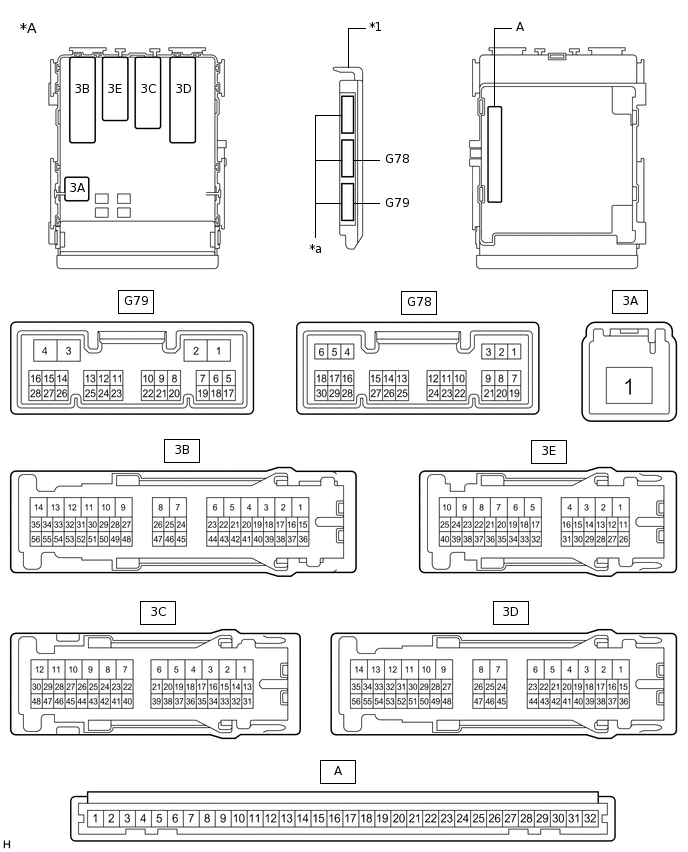
*A
Main body ECU (multiplex network body ECU) with 3 connectors
-
-
*1
Main body ECU (multiplex network body ECU)
-
-
*a
3 connectors
-
-
CHECK MAIN BODY ECU (MULTIPLEX NETWORK BODY ECU) AND INSTRUMENT PANEL JUNCTION BLOCK ASSEMBLY
Remove the main body ECU (multiplex network body ECU) from the instrument panel junction block assembly.
for LHD:
for RHD:
Connect the instrument panel junction block assembly connectors.
Measure the voltage and resistance according to the value(s) in the table below.
Tester Connection
Wiring Color
Terminal Description
Condition
Specified Condition
A-11 (GND1) - Body ground
None - Body ground
Ground
Always
Below 1 Ω
A-29 (ACC) - Body ground
None - Body ground
ACC power supply
Ignition switch ACC
11 to 14 V
Ignition switch off
Below 1 V
A-30 (BECU) - Body ground
None - Body ground
Battery power supply
Always
11 to 14 V
A-32 (IG) - Body ground
None - Body ground
IG power supply
Ignition switch ON
11 to 14 V
Ignition switch off
Below 1 V
A-2 (FLCY) - Body ground
None - Body ground
Front door courtesy light switch assembly LH input signal
Front door LH closed (OFF) → open (ON)
10 kΩ or higher → Below 1 Ω
G78-19 (FRCY) - Body ground
L - Body ground
Front door courtesy light switch assembly RH input signal
Front door RH closed (OFF) → open (ON)
10 kΩ or higher → Below 1 Ω
G78-24 (LCTY) - Body ground
W*1 - Body ground
SB*2 - Body ground
Rear door courtesy light switch assembly LH input signal
Rear door LH closed (OFF) → open (ON)
10 kΩ or higher → Below 1 Ω
G78-6 (RCTY) - Body ground
Y - Body ground
Rear door courtesy light switch assembly RH input signal
Rear door RH closed (OFF) → open (ON)
10 kΩ or higher → Below 1 Ω
A-20 (BCTY) - Body ground
None - Body ground
Back door courtesy light switch signal
Back door closed (OFF) → open (ON)
10 kΩ or higher → Below 1 Ω
G79-5 (HCTY) - Body ground
R - Body ground
Engine hood courtesy switch input signal
Engine hood open (OFF) → closed (ON)
10 kΩ or higher → Below 1 Ω
*1: for LHD
*2: for RHD
Install the main body ECU (multiplex network body ECU) to the instrument panel junction block assembly.
for LHD:
for RHD:
Measure the voltage according to the value(s) in the table below.
Tester Connection
Wiring Color
Terminal Description
Condition
Specified Condition
G78-7 (LSFL) - Body ground
B - Body ground
Front door LH unlock detection switch input signal
Front door LH unlocked
Below 1 V
Ignition switch off, all doors closed and front door LH locked
Pulse generation
G78-18 (LSFR) - Body ground
P - Body ground
Front door RH unlock detection switch input signal
Front door RH unlocked
Below 1 V
Ignition switch off, all doors closed and front door RH locked
Pulse generation
3E-32 (LSR) - Body ground
Y - Body ground
Rear door LH unlock detection switch input signal
Rear door LH unlocked
Below 1 V
Ignition switch off, all doors closed and rear door LH locked
Pulse generation
3C-41 (LSR) - Body ground
Y - Body ground
Rear door RH unlock detection switch input signal
Rear door RH unlocked
Below 1 V
Ignition switch off, all doors closed and rear door RH locked
Pulse generation
3D-53 (SH) - Body ground*4
V - Body ground
Security horn drive
Security horn sounding (Theft deterrent system is in alarm sounding state)
Pulse generation (Below 1 V ←→ 11 to 14 V)
G79-18 (SSCL) - Body ground*1
R - Body ground
Theft warning siren drive
Theft warning siren sounding (Theft deterrent system is in alarm sounding state)
Pulse generation (Below 1 V ←→ 11 to 14 V)
G79-8 (SSW1) - Body ground*2
Y - Body ground
Intrusion sensor cancel switch signal
Intrusion sensor cancel switch on
Below 1 V
Intrusion sensor cancel switch off
Pulse generation
G79-12 (ISIF) - Body ground*2
GR - Body ground
Intrusion sensor (theft warning ultrasonic sensor) signal input
No moving object detected by sensor
11 to 14 V
Moving object detected by sensor during arming preparation state or armed state
Pulse generation
G79-6 (GCS) - Body ground*3
P - Body ground
Communication line between main body ECU (multiplex network body ECU) and tilt sensor
Theft deterrent system changes from armed preparation state to armed state.
The tilt sensor detects pitch angle of vehicle inclination when theft deterrent system is in armed state.
Pulse generation
3D-38 (GPBS) - Body ground*5
R - Body ground
Glass breakage sensor signal
Glass breakage sensor normal
Below 2 V
Glass breakage sensor malfunctioning
4.5 to 14 V
3B-36 (HORN) - Body ground
LG - Body ground
Vehicle horn drive
Vehicle horns sounding (Theft deterrent system is in alarm sounding state)
Pulse generation (Below 1 V ←→ 11 to 14 V)
*1: w/ Theft Warning Siren
*2: w/ Intrusion Sensor
*3: w/ Tilt Sensor
*4: w/ Security Horn Assembly
*5: w/ Glass Breakage Sensor