ELECTRONICALLY CONTROLLED BRAKE SYSTEM(w/ Vacuum Brake Booster), Diagnostic DTC:C1413, C1414
| DTC Code | DTC Name |
|---|---|
| C1413 | Front Speed Sensor RH Output Malfunction |
| C1414 | Front Speed Sensor LH Output Malfunction |
DESCRIPTION
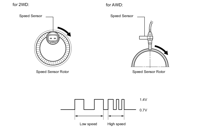
The speed sensor detects wheel speed and sends the appropriate signals to the skid control ECU (brake actuator assembly). These signals are used for brake control.
Speed sensor rotors have rows of alternating N and S magnetic poles, and their magnetic fields change when the rotors turn.
Each speed sensor detects that magnetic change and sends a pulse signal to the skid control ECU (brake actuator assembly).
Tech Tips
When the connectors between the speed sensor and skid control ECU (brake actuator assembly) are connected, the following waveform is output.
| DTC No. | Detection Item | DTC Detection Condition | Trouble Area | Note |
|---|---|---|---|---|
| C1413 | Front Speed Sensor RH Output Malfunction | Any of the following is detected:
|
|
- |
| C1414 | Front Speed Sensor LH Output Malfunction | Any of the following is detected:
|
|
- |
-
*1: for AWD
-
*2: for 2WD
| Vehicle Condition | ||||
|---|---|---|---|---|
| Pattern 1 | Pattern 2 | Pattern 3 | ||
| Diagnosis Condition | - | - | - | - |
| Malfunction Status | An open in the sensor signal circuit of a malfunctioning area occurs 255 times or more | ○ | - | - |
| At a vehicle speed of 20 km/h (12 mph) or more, noise occurs in the sensor signals of a malfunctioning wheel 75 times or more within 5 seconds | - | ○ | - | |
| At a vehicle speed of 10 km/h (6 mph) or more, noise occurs once per rotor rotation | - | - | ○ | |
| Detection Time | - | - | 15 seconds or more. | |
| Number of Trips | 1 trip | 1 trip | 1 trip | |
Tech Tips
DTC will be output when conditions for either of the patterns in the table above are met.
WIRING DIAGRAM
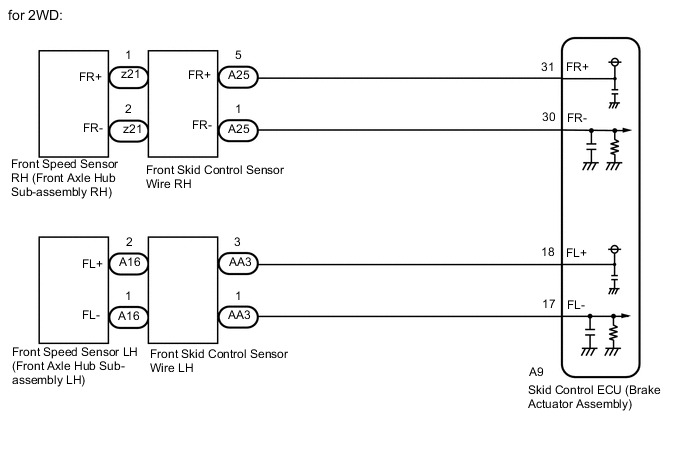
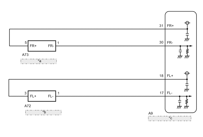
| *a | Front Speed Sensor RH |
| *b | Front Speed Sensor LH |
| *c | Skid Control ECU (Brake Actuator Assembly) |
CAUTION / NOTICE / HINT
Note
When replacing the skid control ECU (brake actuator assembly), perform zero point calibration and store system information.
PROCEDURE
-
CHECK HARNESS AND CONNECTOR (MOMENTARY INTERRUPTION)
-
Using the GTS, check for any momentary interruption in the wire harness and connector corresponding to a DTC.
Chassis > ABS/VSC/TRC > Data ListTester Display Measurement Item Range Normal Condition Diagnostic Note FR Speed Sensor Voltage Open Front speed sensor RH voltage open detection Error or Normal Error: Momentary interruption detected
Normal: Momentary interruption not detected
After a momentary interruption occurs, if there is no momentary interruption for 1 second, it switches from "Error" to "Normal". FL Speed Sensor Voltage Open Front speed sensor LH voltage open detection Error or Normal Error: Momentary interruption detected
Normal: Momentary interruption not detected
After a momentary interruption occurs, if there is no momentary interruption for 1 second, it switches from "Error" to "Normal".
Chassis > ABS/VSC/TRC > Data ListTester Display FR Speed Sensor Voltage Open FL Speed Sensor Voltage Open OK Normal (There are no momentary interruptions.) Tech Tips
Perform the above inspection before removing the sensor and connector.
Result Proceed to OK NG (for 2WD) NG (for AWD)
NG (for 2WD) 
CHECK FRONT SPEED SENSOR INSTALLATION Click here
NG (for AWD)
CHECK FRONT SPEED SENSOR INSTALLATION Click here
OK 
-
-
READ VALUE USING GTS (FRONT SPEED SENSOR)
-
Turn the engine switch off.
-
Connect the GTS to the DLC3.
-
Start the engine.
-
Select the Data List using the GTS.
Chassis > ABS/VSC/TRC > Data ListTester Display Measurement Item Range Normal Condition Diagnostic Note FR Wheel Speed Front wheel speed sensor RH reading Min.: 0 km/h (0 mph), Max.: 326 km/h (202 mph) Vehicle stopped: 0 km/h (0 mph) When driving at constant speed: No large fluctuations FL Wheel Speed Front wheel speed sensor LH reading Min.: 0 km/h (0 mph), Max.: 326 km/h (202 mph) Vehicle stopped: 0 km/h (0 mph) When driving at constant speed: No large fluctuations
Chassis > ABS/VSC/TRC > Data ListTester Display FR Wheel Speed FL Wheel Speed -
Check the speed value output from the speed sensor displayed on the GTS.
Tech Tips
Factors that affect the indicated vehicle speed include tire size, tire pressure, and tire wear. The speed indicated on the speedometer has an allowable margin of error. This can be tested using a speedometer tester (calibrated chassis dynamometer). For details about testing and the margin of error, see the reference chart.
OK The speed value output from the speed sensor displayed on the GTS is similar to the speed indicated on the speedometer. Result Proceed to OK NG (for 2WD) NG (for AWD)
NG (for 2WD)
GO TO STEP 4 Click here
NG (for AWD)
GO TO STEP 8 Click here
OK
-
-
RECONFIRM DTC
-
Clear the DTCs.
Chassis > ABS/VSC/TRC > Clear DTCs -
Turn the engine switch off.
-
Start the engine.
-
Perform a road test.
-
Check if the same DTC is output.
Chassis > ABS/VSC/TRC > Trouble CodesResult Result Proceed to DTCs C1413 and C1414 are not output. A DTCs C1413 and/or C1414 are output. B
A 
USE SIMULATION METHOD TO CHECK Click here
B
REPLACE BRAKE ACTUATOR ASSEMBLY for LHD: Click here
REPLACE BRAKE ACTUATOR ASSEMBLY for RHD: Click here -
-
CHECK FRONT SPEED SENSOR INSTALLATION
-
Turn the engine switch off.
-
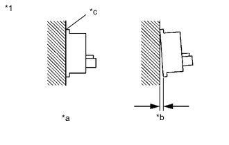
*1 Front Speed Sensor *a Correct *b Incorrect *c No clearance Check the speed sensor installation.
OK There is no clearance between the sensor and the front axle hub sub-assembly. Result Proceed to OK NG
NG
REPLACE FRONT AXLE HUB SUB-ASSEMBLY Click here
OK
-
-
INSPECT FRONT SKID CONTROL SENSOR WIRE
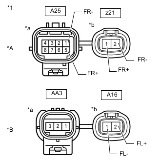
*A for RH *B for LH *1 Front Skid Control Sensor Wire *a Front view of wire harness connector
(to Vehicle Side Connector)
*b Front view of wire harness connector
(to Sensor Side Connector)
-
Make sure that there is no looseness at the locking part and the connecting part of the connectors.
-
Disconnect the z21, A16, A25 and/or AA3 front skid control sensor wire connector.
-
Measure the resistance according to the value(s) in the table below.
Standard Resistance for RH Tester Connection Condition Specified Condition z21 -1 (FR+) - A25 -5 (FR+) Always Below 1 Ω z21 -1 (FR+) or A25 -5 (FR+) - Body ground and other terminals Always 10 MΩ or higher z21 -2 (FR-) - A25 -1 (FR-) Always Below 1 Ω z21 -2 (FR-) or A25 -1 (FR-) - Body ground and other terminals Always 10 MΩ or higher for LH Tester Connection Condition Specified Condition A16 -2 (FL+) - AA3 -3 Always Below 1 Ω A16 -2 (FL+) or AA3 -3 - Body ground and other terminals Always 10 MΩ or higher A16 -1 (FL-) - AA3 -1 Always Below 1 Ω A16 -1 (FL-) or AA3 -1 - Body ground and other terminals Always 10 MΩ or higher Result Proceed to OK NG
NG
REPLACE FRONT SKID CONTROL SENSOR WIRE Click here
OK
-
-
CHECK HARNESS AND CONNECTOR (BRAKE ACTUATOR ASSEMBLY - FRONT SKID CONTROL SENSOR WIRE)
-
Make sure that there is no looseness at the locking part and the connecting part of the connector.
-
Disconnect the A9 skid control ECU (brake actuator assembly) connector.
-
Measure the resistance according to the value(s) in the table below.
Standard Resistance for RH Tester Connection Condition Specified Condition A9-31 (FR+) - A25-5 (FR+) Always Below 1 Ω A9-31 (FR+) or A25-5 (FR+) - Body ground Always 10 kΩ or higher A9-30 (FR-) - A25-1 (FR-) Always Below 1 Ω A9-30 (FR-) or A25-1 (FR-) - Body ground Always 10 kΩ or higher for LH Tester Connection Condition Specified Condition A9-18 (FL+) - AA3 -3 Always Below 1 Ω A9-18 (FL+) or AA3 -3 - Body ground Always 10 kΩ or higher A9-17 (FL-) - AA3 -1 Always Below 1 Ω A9-17 (FL-) or AA3 -1 - Body ground Always 10 kΩ or higher Result Proceed to OK NG
NG
REPAIR OR REPLACE HARNESS OR CONNECTOR
OK
-
-
INSPECT BRAKE ACTUATOR ASSEMBLY (SENSOR INPUT)
-
Reconnect the A9 skid control ECU (brake actuator assembly) connector.
-
Reconnect the AA3 or A25 front skid control sensor wire connector (for vehicle side connector).
-
Turn the engine switch on (IG).
-
Measure the voltage according to the value(s) in the table below.
Standard Voltage for RH Tester Connection Switch Condition Specified Condition z21-1 (FR+) - Body ground Engine switch on (IG) 11 to 14 V for LH Tester Connection Switch Condition Specified Condition A16-2 (FL+) - Body ground Engine switch on (IG) 11 to 14 V Tech Tips
The front speed sensor rotor and front speed sensor are incorporated into the front axle hub sub-assembly.
If the front speed sensor rotor needs to be replaced, replace the front axle hub sub-assembly with front speed sensor.
Result Proceed to OK NG
OK
REPLACE FRONT AXLE HUB SUB-ASSEMBLY Click here
NG
REPLACE BRAKE ACTUATOR ASSEMBLY for LHD: Click here
REPLACE BRAKE ACTUATOR ASSEMBLY for RHD: Click here -
-
CHECK FRONT SPEED SENSOR INSTALLATION
-
Turn the engine switch off.
-
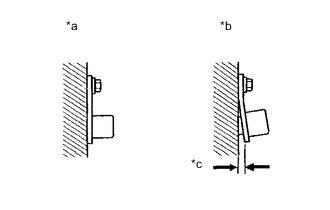
*a Normal *b Abnormal *c Clearance Check the speed sensor installation.
OK There is no clearance between the sensor and the front steering knuckle. The installation bolt is tightened properly. Result Proceed to OK NG
NG
INSTALL FRONT SPEED SENSOR CORRECTLY Click here
OK
-
-
CHECK FRONT SPEED SENSOR AND SENSOR ROTOR
-
Remove the front speed sensor and the component with the sensor rotor.
for speed sensor: Click here
for sensor rotor: Click here
-
Check the speed sensor tip and speed sensor rotor.
OK No scratches, oil, or foreign matter on the sensor tip and rotor. Note
-
If no damage to the speed sensor tip is found during this inspection, do not replace the speed sensor.
If there are any ferrous metal filings stuck to the rotor, this will result in a malfunction, so confirm that the rotor is not contaminated with foreign matter before replacing the sensor.
-
Check the speed sensor signal after cleaning or replacement.
Result Proceed to OK NG -
NG
CLEAN OR REPLACE FRONT SPEED SENSOR OR COMPONENT WITH SENSOR ROTOR
OK
-
-
CHECK HARNESS AND CONNECTOR (BRAKE ACTUATOR ASSEMBLY - FRONT SPEED SENSOR)
-
Install the front speed sensor and the component with the sensor rotor.
-
Make sure that there is no looseness at the locking part and the connecting part of the connector.
-
Disconnect the A9 Skid control ECU (brake actuator assembly) connector.
-
Disconnect the A72 or A73 front speed sensor connector.
-
Measure the resistance according to the value(s) in the table below.
Standard Resistance for RH Tester Connection Condition Specified Condition A9-31 (FR+) - A73-5 (FR+) Always Below 1 Ω A9-31 (FR+) or A73-5 (FR+) - Body ground Always 10 MΩ or higher A9-30 (FR-) - A73-1 (FR-) Always Below 1 Ω A9-30 (FR-) or A73-1 (FR-) - Body ground Always 10 MΩ or higher for LH Tester Connection Condition Specified Condition A9-18 (FL+) - A72-3 (FL+) Always Below 1 Ω A9-18 (FL+) or A72-3 (FL+) - Body ground Always 10 MΩ or higher A9-17 (FL-) - A72-1 (FL-) Always Below 1 Ω A9-17 (FL-) or A72-1 (FL-) - Body ground Always 10 MΩ or higher Result Proceed to OK NG
NG
REPAIR OR REPLACE HARNESS OR CONNECTOR
OK
-
-
INSPECT BRAKE ACTUATOR ASSEMBLY (SENSOR INPUT)
-
Reconnect the A9 skid control ECU (brake actuator assembly) connector.
-
Turn the engine switch on (IG).
-
Measure the voltage according to the value(s) in the table below.
Standard Voltage for RH Tester Connection Condition Specified Condition A73-5 (FR+) - Body ground Engine switch on (IG) 11 to 14 V for LH Tester Connection Condition Specified Condition A72-3 (FL+) - Body ground Engine switch on (IG) 11 to 14 V Result Proceed to OK NG
OK
REPLACE FRONT SPEED SENSOR Click here
NG
REPLACE BRAKE ACTUATOR ASSEMBLY for LHD: Click here
REPLACE BRAKE ACTUATOR ASSEMBLY for RHD: Click here -