INSTRUMENT PANEL SAFETY PAD REMOVAL
CAUTION / NOTICE / HINT
The necessary procedures (adjustment, calibration, initialization, or registration) that must be performed after parts are removed, installed, or replaced during the instrument panel safety pad sub-assembly removal/installation are shown below.
| Replacement Part or Procedure | Necessary Procedure | Effect/Inoperative when not Performed | Link |
|---|---|---|---|
| Disconnect cable from negative battery terminal | Memorize steering angle neutral point | Lane departure alert system (w/ Steering Control) | |
| Simple intelligent parking assist system*1 | |||
| Toyota parking assist-sensor system (w/ Simple Intelligent Parking Assist System)*1 | |||
| Pre-collision system | |||
| Initialize back door lock | Power door lock control system | ||
| Drive the vehicle until stop and start control is permitted (approximately 5 to 60 minutes)*2 | Stop and start system |
*1: When performing learning using the GTS.
*2: w/ Stop and start system
CAUTION:
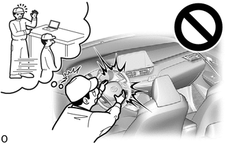
Some of these service operations affect the SRS airbag system. Read the precautionary notices concerning the SRS airbag system before servicing.
Tech Tips
-
Use the same procedure for LHD and RHD vehicles.
-
The procedure listed below is for the LHD vehicles.
PROCEDURE
-
TABLE OF BOLT, SCREW AND NUT
Tech Tips
All bolts and screws relevant to installing and removing the instrument panel are shown along with their alphabetic code in the table below.
-
for TMMT Made:
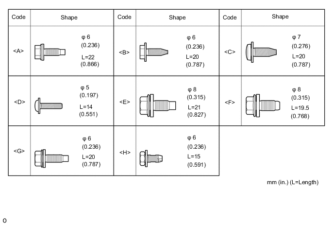
-
except TMMT Made:
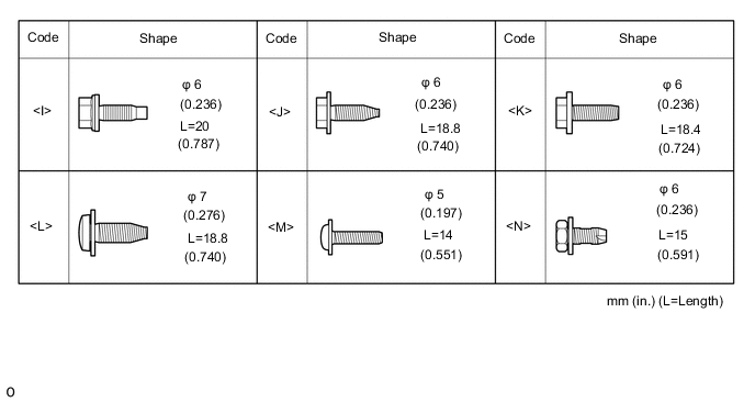
-
-
PRECAUTION
Note
After turning the ignition switch off, waiting time may be required before disconnecting the cable from the negative (-) battery terminal. Therefore, make sure to read the disconnecting the cable from the negative (-) battery terminal notices before proceeding with work.
-
DISCONNECT CABLE FROM NEGATIVE BATTERY TERMINAL
-
for 8NR-FTS
-
for 3ZR-FAE
CAUTION:
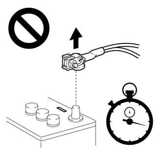
Wait at least 90 seconds after disconnecting the cable from the negative (-) battery terminal to disable the SRS system.
Note
When disconnecting the cable, some systems need to be initialized after the cable is reconnected.
-
-
REMOVE REAR CONSOLE BOX ASSEMBLY
-
REMOVE HEADLIGHT DIMMER SWITCH ASSEMBLY
-
REMOVE FRONT DOOR SCUFF PLATE RH
-
REMOVE COWL SIDE TRIM BOARD RH
-
REMOVE NO. 2 INSTRUMENT PANEL UNDER COVER SUB-ASSEMBLY
-
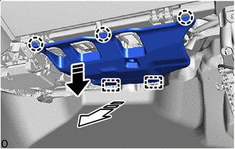

Remove in this Direction (1) 
Remove in this Direction (2) Disengage the claws and guides to remove the No. 2 instrument panel under cover sub-assembly as shown in the illustration.
-
-
REMOVE GLOVE COMPARTMENT DOOR ASSEMBLY
-
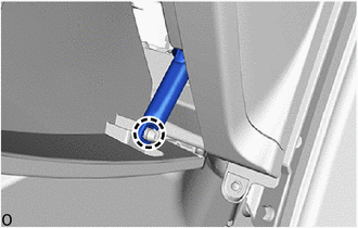
Disengage the claw to disconnect the glove compartment door stopper sub-assembly.
-
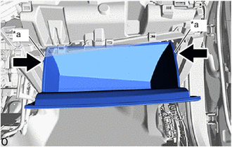
*a Stopper Portion 
Push Disengage the stoppers and pull out the glove compartment door assembly until it is level.
-
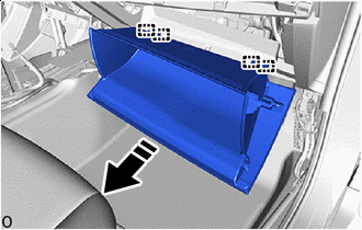
Remove in this Direction Disengage the hinges to remove the glove compartment door assembly as shown in the illustration.
-
-
REMOVE GLOVE COMPARTMENT DOOR STOPPER SUB-ASSEMBLY
-
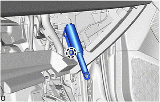
Disengage the claw to remove the glove compartment door stopper sub-assembly.
-
-
REMOVE NO. 2 INSTRUMENT PANEL LOWER FINISH PANEL
-
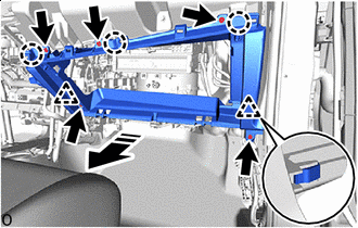
Remove in this Direction Remove the 5 screws <D> or 5 screws <M>.
-
Disengage the clips and claws to remove the No. 2 instrument panel lower finish panel as shown in the illustration.
-
Disconnect the connector.
-
-
DISCONNECT FRONT DOOR OPENING TRIM WEATHERSTRIP LH
-
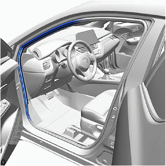
Disconnect the front door opening trim weatherstrip LH from the area shown in the illustration.
-
-
DISCONNECT FRONT DOOR OPENING TRIM WEATHERSTRIP RH
Tech Tips
Use the same procedure as for the LH side.
-
REMOVE INSTRUMENT PANEL FINISH END PANEL LH
-
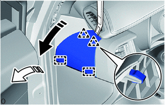
Remove in this Direction (1) Remove in this Direction (2) Using a molding remover A, disengage the clips and guides to remove the instrument panel finish end panel LH as shown in the illustration.
-
-
REMOVE INSTRUMENT PANEL FINISH END PANEL RH
Tech Tips
Use the same procedure as for the LH side.
-
REMOVE INSTRUMENT SIDE PANEL LH
-
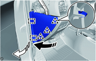
Remove in this Direction (1) Remove in this Direction (2) Using a molding remover A, disengage the clips and guides to remove the instrument side panel LH as shown in the illustration.
-
w/ Airbag Cut Off Switch:
-
Disconnect the connector.
-
-
-
REMOVE INSTRUMENT SIDE PANEL RH
Tech Tips
Use the same procedure as for the LH side.
-
REMOVE FRONT PILLAR GARNISH LH
-
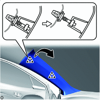
Pull up Pull up the front pillar garnish LH to disengage the clips as shown in the illustration.
-
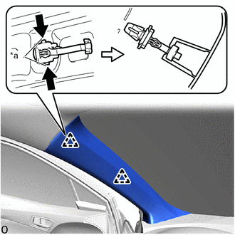
*a Release Lever Push Push the release lever and separate the front pillar garnish clips from the vehicle body as shown in the illustration.
Note
If the front pillar garnish clip has significant damage, replace it with a new one.
-
When the front pillar garnish clip cannot be removed using your fingers:
-
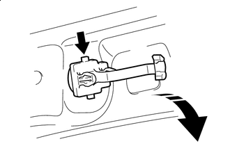
Lift in this Direction While pressing the part shown in the illustration with your finger, move the front pillar garnish clip in the direction indicated by the arrow shown in the illustration.
-
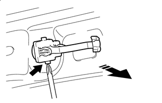
Remove in this Direction While pulling the front pillar garnish clip in the direction indicated by the arrow, push the part shown in the illustration with the end of a screwdriver and remove the front pillar garnish clip.
Note
If the front pillar garnish clip has significant damage, replace it with a new one.
-
-
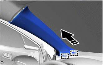
Remove in this Direction Disengage the guides to remove the front pillar garnish LH as shown in the illustration.
-
w/ Speaker:
-
Disconnect the connector.
-
-
Remove the front pillar garnish clip.
-
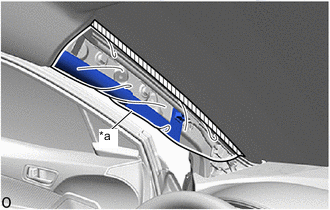
*a Protective Cover 
Adhesive Tape Protect the curtain shield airbag assembly.
-
Completely cover the curtain shield airbag assembly with a cloth or nylon sheet and secure the ends of the cover with adhesive tape as shown in the illustration.
Note
Cover the curtain shield airbag assembly with a protective cover as soon as the front pillar garnish LH is removed.
-
-
-
REMOVE FRONT PILLAR GARNISH RH
Tech Tips
Use the same procedure as for the LH side.
-
REMOVE NO. 1 INSTRUMENT PANEL SPEAKER PANEL SUB-ASSEMBLY
-
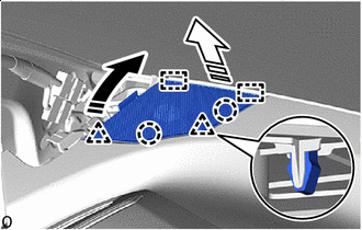
Remove in this Direction (1) Remove in this Direction (2) Disengage the clips, claws and guides to remove the No. 1 instrument panel speaker panel sub-assembly as shown in the illustration.
-
w/ Speaker:
-
Disconnect the connector.
-
-
-
REMOVE NO. 2 INSTRUMENT PANEL SPEAKER PANEL SUB-ASSEMBLY
Tech Tips
Use the same procedure as for the No. 1 instrument panel speaker panel sub-assembly side.
-
REMOVE NO. 2 FRONT SPEAKER ASSEMBLY (w/ Woofer)
-
REMOVE INSTRUMENT CLUSTER FINISH PANEL SUB-ASSEMBLY
-
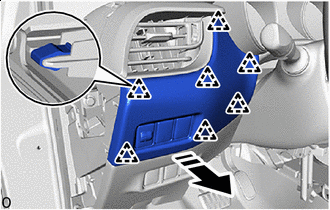
Remove in this Direction Disengage the clips to remove the instrument cluster finish panel sub-assembly as shown in the illustration.
-
w/ Switch:
-
Disconnect each connector.
-
-
-
REMOVE INSTRUMENT CLUSTER FINISH PANEL ASSEMBLY
-
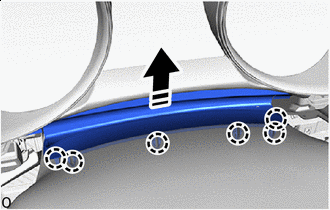
Remove in this Direction Disengage the claws to separate the meter hood spacer as shown in the illustration.
-
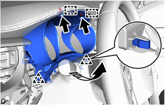
Remove in this Direction Remove the 2 clips.
-
Disengage the clips and guides to remove the instrument cluster finish panel assembly as shown in the illustration.
-
-
REMOVE NO. 2 INSTRUMENT PANEL GARNISH SUB-ASSEMBLY
-
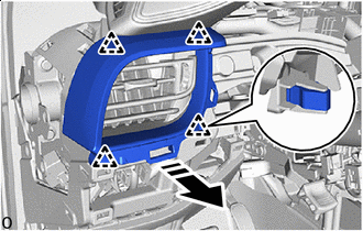
Remove in this Direction Disengage the clips to remove the No. 2 instrument panel garnish sub-assembly as shown in the illustration.
-
-
REMOVE STARTER SWITCH BEZEL (for RHD with Entry and Start System)
-
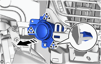
Remove in this Direction Disengage the clips to remove the starter switch bezel as shown in the illustration.
-
Disconnect the connector.
-
-
REMOVE COMBINATION METER ASSEMBLY
-
DISCONNECT HOOD LOCK CONTROL LEVER SUB-ASSEMBLY
-
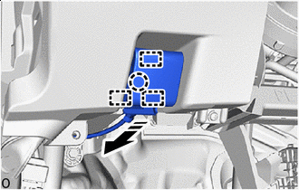
Remove in this Direction Disengage the claw and guides to disconnect the hood lock control lever sub-assembly as shown in the illustration.
-
-
REMOVE FUSE BOX OPENING COVER (w/ Knee Airbag)
-
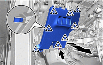
Remove in this Direction Remove the screw <D> or screw <M>.
-
Disengage the clips to remove the fuse box opening cover as shown in the illustration.
-
Disconnect each connector.
-
-
REMOVE LOWER NO. 1 INSTRUMENT PANEL AIRBAG ASSEMBLY WITH DOOR (w/ Knee Airbag)
-
REMOVE FUSE BOX OPENING COVER (w/o Knee Airbag)
-
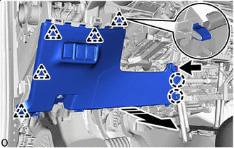
Remove in this Direction Remove the screw <D> or screw <M>.
-
Disengage the clips and claws to remove the fuse box opening cover with instrument panel lower finish panel sub-assembly as shown in the illustration.
-
Disconnect each connector.
-
-
REMOVE INSTRUMENT PANEL LOWER FINISH PANEL SUB-ASSEMBLY (w/o Knee Airbag)
-
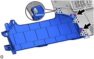
Remove the 2 screws <D> or 2 screws <M>.
-
Disengage the clips to remove the instrument panel lower finish panel sub-assembly from the fuse box opening cover.
-
-
REMOVE INSTRUMENT CLUSTER FINISH CENTER PANEL SUB-ASSEMBLY (w/o Display)
-
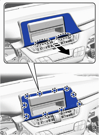

Place Hands Here Remove in this Direction Disengage the claws to remove the instrument cluster finish center panel sub-assembly as shown in the illustration.
-
-
REMOVE RADIO RECEIVER ASSEMBLY WITH BRACKET (for Radio Receiver Type)
-
REMOVE STEREO OPENING COVER WITH BRACKET (w/ Cover)
-
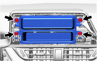
Remove the 4 bolts <G> or 4 bolts <I>.
-
Disengage the guides to remove the stereo opening cover with bracket.
-
Disconnect the connector.
-
-
REMOVE NO. 1 RADIO BRACKET (w/ Cover)
-
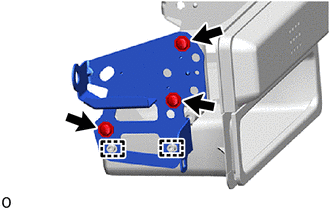
Remove the 3 screws <D> or 3 screws <M>.
-
Disengage the guides to remove the No. 1 radio bracket.
-
-
REMOVE NO. 2 RADIO BRACKET (w/ Cover)
-
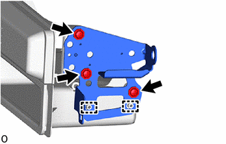
Remove the 3 screws <D> or 3 screws <M>.
-
Disengage the guides to remove the No. 2 radio bracket.
-
-
REMOVE NO. 1 RADIO BRACKET (w/o Cover)
-
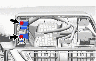
Remove the 2 bolts <G> or 2 bolts <I>.
-
Disengage the guides to remove the No. 1 radio bracket.
-
-
REMOVE NO. 2 RADIO BRACKET (w/o Cover)
-
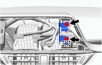
Remove the 2 bolts <G> or 2 bolts <I>.
-
Disengage the guides to remove the No. 2 radio bracket.
-
-
REMOVE INSTRUMENT CLUSTER FINISH LOWER CENTER PANEL SUB-ASSEMBLY
-
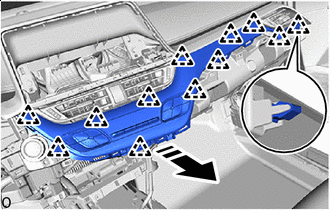
Remove in this Direction Disengage the clips to remove the instrument cluster finish lower center panel sub-assembly as shown in the illustration.
-
Disconnect the connector.
-
-
REMOVE STARTER SWITCH BEZEL (for LHD with Entry and Start System)
-
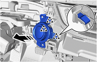
Remove in this Direction Disengage the clips to remove the starter switch bezel as shown in the illustration.
-
Disconnect the connector.
-
-
REMOVE NO. 1 INSTRUMENT PANEL GARNISH SUB-ASSEMBLY (w/o Display)
-
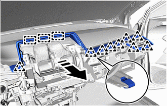
Remove in this Direction Disengage the clips and guides to remove the No. 1 instrument panel garnish sub-assembly as shown in the illustration.
-
-
REMOVE INSTRUMENT PANEL CENTER REGISTER ASSEMBLY
-
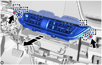
Remove in this Direction Remove the 2 screws <D> or 2 screws <M>.
-
Disengage the claws and guides to remove the instrument panel center register assembly as shown in the illustration.
-
-
REMOVE RADIO AND DISPLAY RECEIVER ASSEMBLY WITH BRACKET (for Radio and Display Type)
-
REMOVE NO. 1 INSTRUMENT PANEL GARNISH SUB-ASSEMBLY (w/ Display)
-
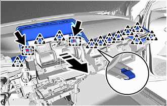
Remove in this Direction Remove the 2 bolts <G>.
-
Disengage the clips and guides to remove the No. 1 instrument panel garnish sub-assembly as shown in the illustration.
-
-
REMOVE NO. 2 HEATER TO REGISTER DUCT SUB-ASSEMBLY
-
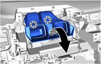
Remove in this Direction Disengage the claws to remove the No. 2 heater to register duct sub-assembly as shown in the illustration.
-
-
REMOVE INSTRUMENT PANEL SAFETY PAD SUB-ASSEMBLY
-
for TMMT Made:
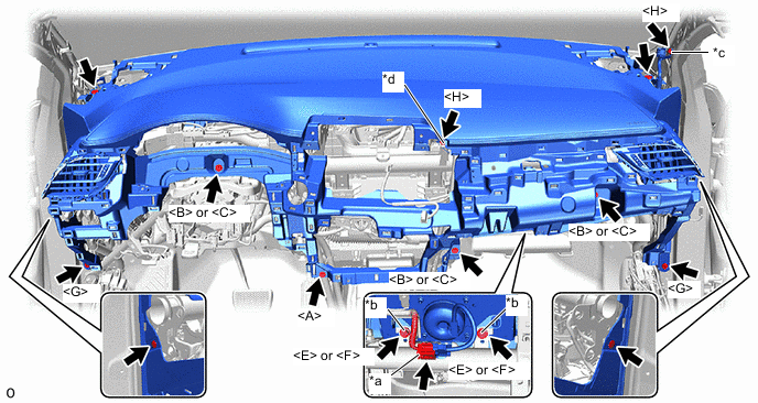
*a Slider *b Airbag Bolt *c Ground Bolt A *d Ground Bolt B
-
Remove the 4 clips.
-
Remove the 10 bolts as shown in the illustration.
-
Slide the slider to disconnect the airbag connector.
-
-
except TMMT Made:
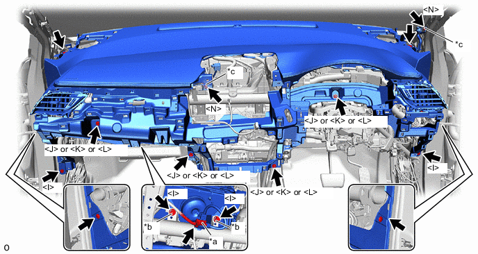
*a Slider *b Airbag Bolt *c Ground Bolt - -
-
Remove the 4 clips.
-
Remove the 10 bolts as shown in the illustration.
-
Slide the slider to disconnect the airbag connector.
-
-
Disconnect each connector.
-
Disengage each clamp.
-
Disengage the guides to remove the instrument panel safety pad sub-assembly as shown in the illustration.
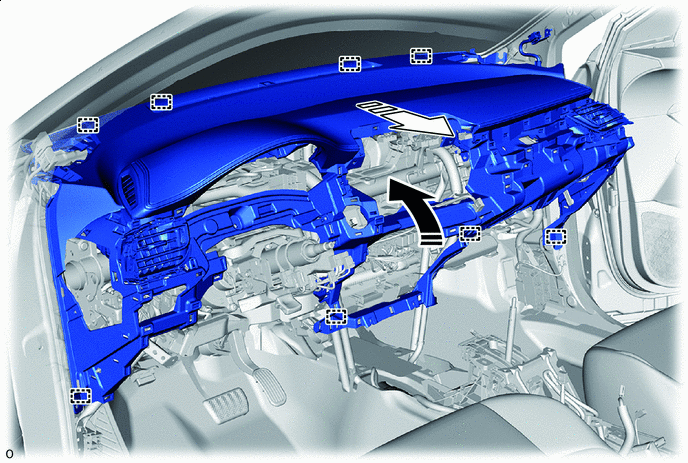
Remove in this Direction (1) Remove in this Direction (2)
-