EXHAUST GAS TEMPERATURE SENSOR INSTALLATION
PROCEDURE
INSTALL NO. 2 EXHAUST GAS TEMPERATURE SENSOR
Note:If the No. 2 exhaust gas temperature sensor is dropped, replace it with a new one.
Using a 14 mm union nut wrench, install the No. 2 exhaust gas temperature sensor.
30 N*m
306 kgf*cm
22 ft.*lbf
Note:Use the formula to calculate special torque values for situations where a union nut wrench is combined with a torque wrench.
Attach the No. 2 exhaust gas temperature sensor connector clamp.
INSTALL NO. 3 EXHAUST GAS TEMPERATURE SENSOR
Note:If the No. 3 exhaust gas temperature sensor is dropped, replace it with a new one.
-
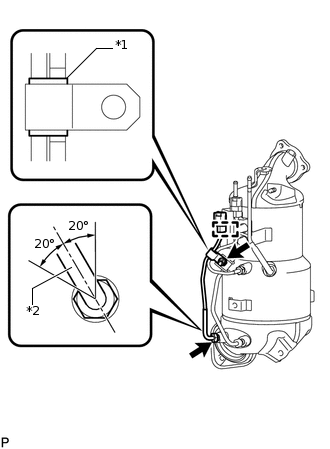
*1
White Tube
*2
Protective Tube
Temporarily install the No. 3 exhaust gas temperature sensor with the union nut.
Attach the No. 3 exhaust gas temperature sensor connector clamp.
Temporarily install the clamp with the nut.
Note:Make sure the clamp is aligned with the white tube of the wire harness as shown in the illustration.
Tighten the nut.
6.4 N*m
65 kgf*cm
57 in.*lbf
Using a 14 mm union nut wrench, tighten the union nut of the No. 3 exhaust gas temperature sensor.
30 N*m
306 kgf*cm
22 ft.*lbf
Note:When tightening the union nut, make sure that the protective tube of the No. 3 exhaust gas temperature sensor is within the range shown in the illustration.
Use the formula to calculate special torque values for situations where a union nut wrench is combined with a torque wrench.
-
INSTALL EXHAUST MANIFOLD CONVERTER SUB-ASSEMBLY
INSTALL NO. 4 MANIFOLD CONVERTER INSULATOR
INSTALL ENGINE ASSEMBLY
INSTALL EXHAUST GAS TEMPERATURE SENSOR
Note:If the exhaust gas temperature sensor is dropped, replace it with a new one.
Using a 14 mm union nut wrench, install the exhaust gas temperature sensor.
30 N*m
306 kgf*cm
22 ft.*lbf
Note:Use the formula to calculate special torque values for situations where a union nut wrench is combined with a torque wrench.
Attach the exhaust gas temperature sensor connector clamp and connect the exhaust gas temperature sensor connector.
INSTALL NO. 1 ENGINE COVER