VACUUM PUMP INSTALLATION
PROCEDURE
-
INSTALL VACUUM PUMP ASSEMBLY
-
When using a new vacuum pump assembly:
-
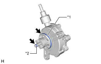
*1 No. 2 O-ring *2 No. 3 O-ring 
Engine Oil Apply engine oil to the No. 2 O-ring and No. 3 O-ring which are installed to a new vacuum pump assembly.
-
-
When reusing the vacuum pump assembly:
-
*1 No. 2 O-ring *2 No. 3 O-ring Engine Oil Apply engine oil to a new No. 2 O-ring and No. 3 O-ring and install them to the vacuum pump assembly.
-
-
Apply engine oil to the inner surface of the installation hole.
-
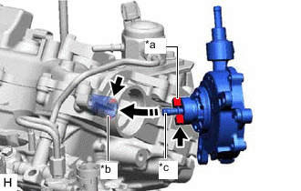
*a Coupling Teeth *b Groove *c Oil Pipe Temporarily install the vacuum pump assembly so that the oil pipe engages with the hole of the camshaft and the coupling teeth engages with the groove of the camshaft.
Note
-
Ensure that the vacuum pump assembly is installed securely.
-
Be careful not to pinch the O-ring.
-
-
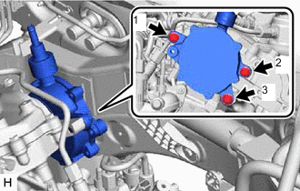
Install the vacuum pump assembly with the 3 bolts.
- Torque:
- 21 N*m { 214 kgf*cm, 15 ft.*lbf }
Note
-
After installation, check that there are no gaps between the matching surfaces and that the vacuum pump assembly is not installed at an angle.
-
Tighten the 3 bolts in the order shown in the illustration.
-
-
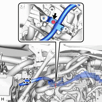
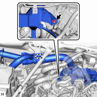
CONNECT NO. 12 WATER BY-PASS HOSE
-
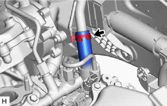
Connect the No. 12 water by-pass hose to the No. 2 water by-pass pipe and slide the clip to secure it.
-
-
CONNECT UNION TO CHECK VALVE HOSE
-
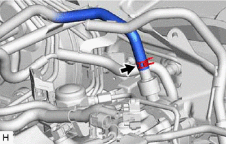
Connect the union to check valve hose to the vacuum pump assembly and slide the clip to secure it.
-
-
INSTALL NO. 2 ENGINE WIRE (for LHD)
-
Install the No. 2 engine wire with the bolt.
- Torque:
- 10 N*m { 102 kgf*cm, 7 ft.*lbf }
-
Attach the clamp.
-
-
CONNECT ENGINE WIRE (for LHD)
-
Install the engine wire with the nut.
- Torque:
- 10 N*m { 102 kgf*cm, 7 ft.*lbf }
-
Attach the clamp.
-
-
CONNECT OUTLET HEATER WATER HOSE
-
CONNECT INLET HEATER WATER HOSE
-
REMOVE INTAKE AIR SURGE TANK ASSEMBLY
-
INSTALL NO. 1 HOSE TO HOSE TUBE (for LHD)
-
INSTALL THROTTLE BODY WITH MOTOR ASSEMBLY
-
INSTALL COWL TOP VENTILATOR LOUVER SUB-ASSEMBLY
-
INSPECT VACUUM PUMP OPERATION