SFI SYSTEM, Diagnostic DTC:P0812
| DTC Code | DTC Name |
|---|---|
| P0812 | Reverse Input Circuit |
DESCRIPTION
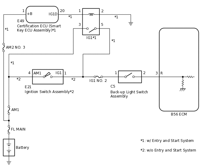
The back-up light switch assembly is mounted on the manual transaxle. The switch is turned on when selecting the shift lever in reverse position, and transmits a signal to the ECM.
DTC No. |
Detection Item |
DTC Detection Condition |
Trouble Area |
MIL |
Memory |
|---|---|---|---|---|---|
P0812 |
Reverse Input Circuit |
Abnormal back-up light switch assembly signal input to ECM. |
|
Does not come on |
DTC stored |
MONITOR DESCRIPTION
This DTC is stored when a malfunction is detected in the back-up light switch assembly circuit. If the back-up light switch assembly signal is not received when the vehicle is in reverse, the ECM will store this DTC.
WIRING DIAGRAM
CAUTION / NOTICE / HINT
Inspect the fuses for circuits related to this system before performing the following procedure.
PROCEDURE
INSPECT BACK-UP LIGHT SWITCH ASSEMBLY
Inspect the back-up light switch assembly.
Result
Proceed to
OK
NG
CHECK SWITCH INSTALLATION (BACK-UP LIGHT SWITCH ASSEMBLY)
Check the back-up light switch assembly installation.
OK
The switch is installed correctly.
Result
Proceed to
OK
NG
CHECK TERMINAL VOLTAGE (POWER SOURCE OF BACK-UP LIGHT SWITCH ASSEMBLY)
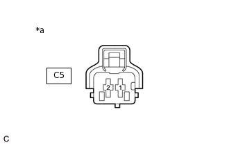
*a
Front view of wire harness connector
(to Back-up Light Switch Assembly )
Disconnect the back-up light switch assembly connector.
Turn the ignition switch to ON.
Measure the voltage according to the value(s) in the table below.
Standard Voltage
Tester Connection
Condition
Specified Condition
C5-1 - Body ground
Ignition switch ON
11 to 14 V
Result
Result
Proceed to
OK
A
NG (w/ Entry and Start System)
B
NG (w/o Entry and Start System)
C
B REPAIR OR REPLACE HARNESS OR CONNECTOR (BACK-UP LIGHT SWITCH ASSEMBLY - IG1 RELAY)
C REPAIR OR REPLACE HARNESS OR CONNECTOR (BACK-UP LIGHT SWITCH ASSEMBLY - IGNITION SWITCH ASSEMBLY)
CHECK HARNESS AND CONNECTOR (BACK-UP LIGHT SWITCH ASSEMBLY - ECM)
Disconnect the back-up light switch assembly connector.
Disconnect the ECM connector.
Measure the resistance according to the value(s) in the table below.
Standard Resistance
Tester Connection
Condition
Specified Condition
C5-2 - B56-3 (R)
Always
Below 1 Ω
C5-2 or B56-3 (R) - Body ground and other terminals
Always
10 kΩ or higher
Result
Proceed to
OK
NG
NG REPAIR OR REPLACE HARNESS OR CONNECTOR