ECD SYSTEM(for CCo), Diagnostic DTC:P1229
| DTC Code | DTC Name |
|---|---|
| P1229 | Fuel Pump System |
DESCRIPTION
DTC No. |
Detection Item |
DTC Detection Condition |
Trouble Area |
MIL |
Memory |
|---|---|---|---|---|---|
P1229 |
Fuel Pump System |
The actual fuel pressure exceeds the target fuel pressure by 5000 kPa or higher for 30 seconds. (1 trip detection logic) |
|
Comes on |
DTC stored |
DTC No. |
Data List |
|---|---|
P1229 |
|
For more information on the fuel supply pump assembly (suction control valve) and common rail system, refer to System Description (Click here).
When DTC P1229 is stored, check the internal fuel pressure of the common rail by entering the following menus: Powertrain / Engine and ECT / Data List / Fuel Press, Target Common Rail Pressure.
Under a stable condition such as idling after warm up the engine, Fuel Press is within +/- 5000 kPa of Target Common Rail Pressure when normal.
When there is a problem with the movement of the fuel supply pump assembly (when Fuel Press is higher than Target Common Rail Pressure due to a problem in which the suction valve has difficulty closing), the values of Injection Pressure Correction and Target Pump SCV Current decrease.
MONITOR DESCRIPTION
P1229 (Fuel over-feed):
The ECM stores this DTC if the actual fuel pressure inside the common rail remains higher than the target fuel pressure, despite the ECM closing the suction control valve. This DTC indicates that the suction control valve may be stuck open, or there may be a short in its circuit.
If this DTC is stored, the ECM enters fail-safe mode and limits the engine power. The fail-safe mode continues until the ignition switch is turned off.
CONFIRMATION DRIVING PATTERN
DTC No. |
DTC Detection Drive Pattern |
|---|---|
P1229 |
Idling for 60 seconds |
WIRING DIAGRAM
CAUTION / NOTICE / HINT
After replacing the ECM, the new ECM needs registration (Click here) and initialization (Click here).
After replacing the fuel supply pump, the ECM needs initialization (Click here).
Read freeze frame data using the GTS. Freeze frame data records the engine condition when malfunctions are detected. When troubleshooting, freeze frame data can help determine if the vehicle was moving or stationary, if the engine was warmed up or not, and other data from the time the malfunction occurred.
When this DTC is stored, be sure to carefully examine "Fuel Press", "Target Common Rail Pressure", "Target Pump SCV Current", and "Pump SCV Learning Value" in the freeze frame data.
PROCEDURE
CHECK OTHER DTC OUTPUT
Connect the GTS to the DLC3.
Turn the ignition switch to ON and turn the GTS on.
Enter the following menus: Powertrain / Engine and ECT / Trouble Codes.
Powertrain > Engine > Trouble Codes
Read the DTCs.
Result
Result
Proceed to
Except above
A
DTC P1229 and "P0190, P0192 and/or P0193" are output
B
READ VALUE USING GTS (FUEL PRESS AND TARGET COMMON RAIL PRESSURE)
Connect the GTS to the DLC3.
Turn the ignition switch to ON and turn the GTS on.
Start the engine and warm it up.
Enter the following menus: Powertrain / Engine and ECT / Data List / Fuel Press and Target Common Rail Pressure.
Powertrain > Engine > Data List
Tester Display
Target Common Rail Pressure
Fuel Press
Check that the internal fuel pressure of the common rail is within the specification below.
OK
Fuel Press is within 5000 kPa of Target Common Rail Pressure when engine is idling after warm up the engine.
Result
Proceed to
OK
NG
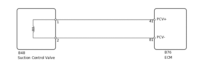
CHECK HARNESS AND CONNECTOR (SUCTION CONTROL VALVE - ECM)
Disconnect the suction control valve connector.
Disconnect the ECM connector.
Measure the resistance according to the value(s) in the table below.
Standard Resistance
Tester Connection
Condition
Specified Condition
B48-1 - B76-41 (PCV+)
Always
Below 1 Ω
B48-2 - B76-81 (PCV-)
Always
Below 1 Ω
B48-1 or B76-41 (PCV+) - Body ground
Always
10 kΩ or higher
B48-2 or B76-81 (PCV-) - Body ground
Always
10 kΩ or higher
Result
Proceed to
OK
NG
OK REPLACE FUEL FILTER ELEMENT ASSEMBLYClick here
REPAIR OR REPLACE HARNESS OR CONNECTOR
Repair or replace the harness or connector.
Result
Proceed to
NEXT
PERFORM ACTIVE TEST USING GTS (TEST THE FUEL LEAK)
Connect the GTS to the DLC3.
Turn the ignition switch to ON and turn the GTS on.
Enter the following menus: Powertrain / Engine and ECT / Active Test / Test the Fuel Leak / Data List / Fuel Press, Target Common Rail Pressure.
Powertrain > Engine > Active Test
Active Test Display
Test the Fuel Leak
Data List Display
Target Common Rail Pressure
Fuel Press
Take a snapshot with the GTS during the Active Test.
Measure the difference between the target fuel pressure (Target Common Rail Pressure) and the actual fuel pressure (Fuel Press) when the "Test the Fuel Leak" Active Test is performed.
Tip:In order to obtain an exact measurement, perform the Active Test 5 times and measure the difference once each time the Active Test is performed.
OK
The difference between the target fuel pressure and the actual fuel pressure 2 seconds after the Active Test starts is less than 10000 kPa.
Result
Result
Proceed to
Except above
A
The difference between the target fuel pressure and the actual fuel pressure 2 seconds after the Active Test starts is less than 10000 kPa.
B
B CONFIRM WHETHER MALFUNCTION HAS BEEN SUCCESSFULLY REPAIREDClick here
REPLACE FUEL FILTER ELEMENT ASSEMBLY
Replace the fuel filter element assembly.
Result
Proceed to
NEXT
REPLACE SUCTION CONTROL VALVE
Replace the Replace the suction control valve.
Result
Proceed to
NEXT
BLEED AIR FROM FUEL SYSTEM
Bleed the air from the fuel system.
Result
Proceed to
NEXT
PERFORM SUPPLY PUMP INITIALIZATION
Perform supply pump initialization.
Result
Proceed to
NEXT
CONFIRM WHETHER MALFUNCTION HAS BEEN SUCCESSFULLY REPAIRED
Connect the GTS to the DLC3.
Turn the ignition switch to ON.
Turn the GTS on.
Clear the DTCs.
Powertrain > Engine > Clear DTCs
Turn the ignition switch off for 30 seconds or more.
Start the engine.
Idle the engine for 60 seconds, and then run it at 2500 rpm without load for 60 seconds.
Enter the following menus: Powertrain / Engine and ECT / Trouble Codes.
Powertrain > Engine > Trouble Codes
Confirm that the DTC is not output again.
Tip:Perform the following procedure using the GTS to determine whether or not the DTC judgment has been carried out.
Enter the following menus: Powertrain / Engine and ECT / Utility / All Readiness.
Powertrain > Engine > Utility
Tester Display
All Readiness
Input DTC P1229.
Check that STATUS is NORMAL. If STATUS is INCOMPLETE or N/A, increase the idling time.
Result
Proceed to
NEXT
NEXT END