LIGHTING SYSTEM Headlight (HI-BEAM) Circuit
| DTC Code | DTC Name |
|---|---|
| Headlight (HI-BEAM) Circuit |
DESCRIPTION
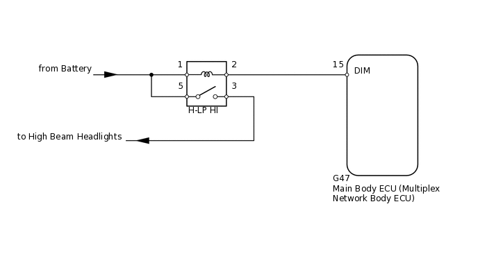
The main body ECU receives headlight dimmer switch information signals and illuminates the high beam headlights.
WIRING DIAGRAM
CAUTION / NOTICE / HINT
Inspect the fuses and bulbs for circuits related to this system before performing the following inspection procedure.
PROCEDURE
PERFORM ACTIVE TEST USING INTELLIGENT TESTER (HIGH BEAM HEADLIGHT)
Using the intelligent tester, perform the Active Test.
Body Electrical > Main Body > Active Test
Tester Display
Measurement Item
Control Range
Diagnostic Note
Head Light Hi
High beam headlight relay
ON/OFF
-
OK
Relay operates (high beam headlights illuminate).
Result
Result
OK
NG
INSPECT HEADLIGHT RELAY (H-LP HI)
-
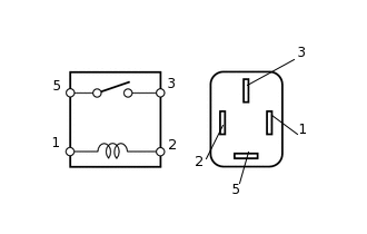
Remove the headlight dimmer relay from the engine room relay block.
Measure the resistance according to the value(s) in the table below.
Standard Resistance
Tester Connection
Condition
Specified Condition
3 - 5
Battery voltage not applied between terminals 1 and 2
10 kΩ or higher
3 - 5
Battery voltage applied between terminals 1 and 2
Below 1 Ω
Result
Result
OK
NG
NG REPLACE HEADLIGHT DIMMER RELAY
-
CHECK HARNESS AND CONNECTOR (BATTERY - HEADLIGHT DIMMER RELAY [H-LP HI])
-
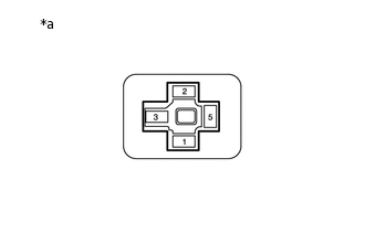
*a
Front view of wire harness connector
(to Headlight Dimmer Relay)
Measure the voltage according to the value(s) in the table below.
Standard Voltage
Tester Connection
Condition
Specified Condition
Headlight dimmer relay terminal 1 - Body ground
Always
11 to 14 V
Headlight dimmer relay terminal 5 - Body ground
Result
Result
OK
NG
NG REPAIR OR REPLACE HARNESS OR CONNECTOR
-
CHECK HARNESS AND CONNECTOR (HEADLIGHT DIMMER RELAY [H-LP HI] - MAIN BODY ECU AND BODY GROUND)
Disconnect the G47 main body ECU connector.
Measure the resistance according to the value(s) in the table below.
Standard Resistance
Tester Connection
Condition
Specified Condition
Headlight dimmer relay terminal 2 - G47-15 (DIM)
Always
Below 1 Ω
G47-15 (DIM) - Body ground
Always
10 kΩ or higher
Result
Result
OK
NG
NG REPAIR OR REPLACE HARNESS OR CONNECTOR