STEERING COLUMN ASSEMBLY INSTALLATION
PROCEDURE
INSPECT STEERING COLUMN ASSEMBLY
INSTALL STEERING COLUMN ASSEMBLY
-
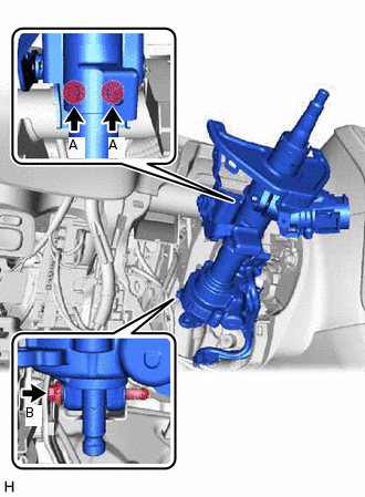
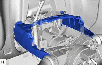
Install the steering column assembly with the 3 bolts.
25.0 N*m
255 kgf*cm
18 ft.*lbf
Note:Make sure that the wire harness is not interfering with the steering column assembly.
Tip:Bolt (A) is shorter than bolt (B).
Connect each connector and engage each wire harness clamp to the steering column assembly.
-
INSTALL STOP LIGHT SWITCH ASSEMBLY
INSTALL NO. 2 STEERING INTERMEDIATE SHAFT ASSEMBLY
-
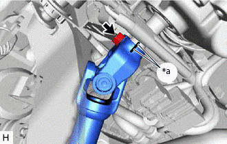
*a
Matchmark
Align the matchmarks on the No. 2 steering intermediate shaft assembly and steering column assembly.
Install the No. 2 steering intermediate shaft assembly to the steering column assembly.
Install the bolt.
35.3 N*m
360 kgf*cm
26 ft.*lbf
-
CONNECT NO. 2 STEERING INTERMEDIATE SHAFT ASSEMBLY
-
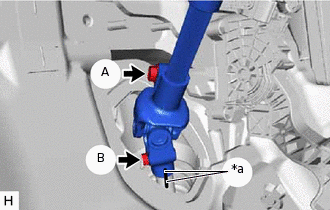
*a
Matchmark
Align the matchmarks on the No. 2 steering intermediate shaft assembly and steering gear assembly.
Connect the No. 2 steering intermediate shaft assembly to the steering gear assembly.
Install the bolt (B).
35.3 N*m
360 kgf*cm
26 ft.*lbf
Tighten the bolt (A).
35.3 N*m
360 kgf*cm
26 ft.*lbf
-
INSTALL STEERING COLUMN HOLE COVER PLATE
Engage the 2 claws to install the steering column hole cover plate.
Install the floor carpet.
INSTALL POWER STEERING ECU ASSEMBLY
INSTALL TURN SIGNAL SWITCH ASSEMBLY WITH SPIRAL CABLE SUB-ASSEMBLY
Note:w/ VSC:
Do not replace the spiral cable with sensor sub-assembly with the battery connected and the ignition switch ON.
Do not rotate the spiral cable with sensor sub-assembly without the steering wheel assembly with the battery connected and the ignition switch ON.
Ensure that the steering wheel assembly is installed and aligned straight when inspecting the steering sensor.
-
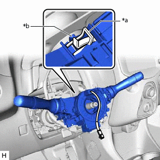
*a
Clamp
*b
Claw
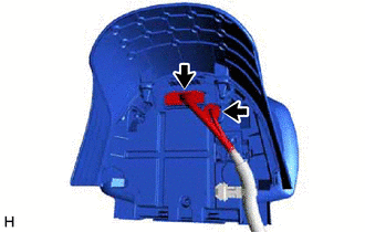
Using pliers, expand the clamp.
While holding the clamp expanded, install the turn signal switch assembly with spiral cable sub-assembly to the steering column assembly and engage the claw.
Return the clamp to its original position.
Connect each connector to the turn signal switch assembly with spiral cable sub-assembly.
INSTALL UPPER NO. 1 STEERING COLUMN COVER
-
Install the upper No. 1 steering column cover.
-
INSTALL COMBINATION METER ASSEMBLY
-
Connect the 2 connectors to the combination meter assembly.
-
Install the combination meter assembly to the steering column assembly with the 2 bolts.
-
INSTALL UPPER NO. 2 STEERING COLUMN COVER
-
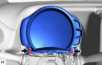
Engage the 2 claws to install the upper No. 2 steering column cover.
-
INSTALL LOWER STEERING COLUMN COVER
-
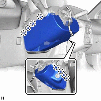
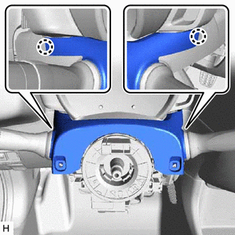
Engage the 8 claws to install the lower steering column cover.
-
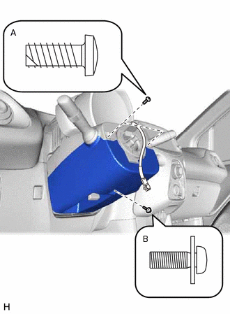
Install the 2 screws (A).
2.0 N*m
20 kgf*cm
18 in.*lbf
Install the screw (B).
2.0 N*m
20 kgf*cm
18 in.*lbf
-
ALIGN FRONT WHEELS FACING STRAIGHT AHEAD
INSPECT AND ADJUST SPIRAL CABLE WITH SENSOR SUB-ASSEMBLY
INSTALL STEERING WHEEL ASSEMBLY
CHECK STEERING WHEEL CENTER POINT
INSTALL HORN BUTTON ASSEMBLY
PERFORM CALIBRATION OF TORQUE SENSOR ZERO POINT