REAR VIEW MONITOR SYSTEM (for Navigation Receiver Type) Display Signal Circuit between Navigation Receiver Assembly and Television Camera Assembly
DESCRIPTION
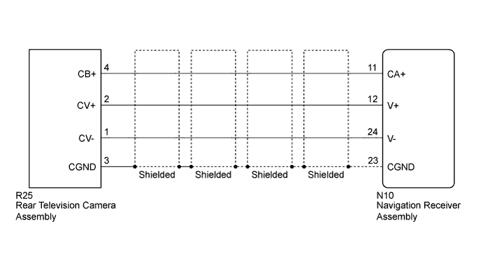
This is the display signal circuit between the navigation receiver assembly and the rear television camera assembly.
WIRING DIAGRAM
INSPECTION PROCEDURE
PROCEDURE
-
CHECK HARNESS AND CONNECTOR (NAVIGATION RECEIVER ASSEMBLY - REAR TELEVISION CAMERA ASSEMBLY)
-
Disconnect the N10 navigation receiver assembly connector.
-
Disconnect the R25 rear television camera assembly connector.
-
Measure the resistance according to the value(s) in the table below.
Standard Resistance Tester Connection Condition Specified Condition N10-11 (CA+) - R25-4 (CB+) Always Below 1 Ω N10-12 (V+) - R25-2 (CV+) Always Below 1 Ω N10-23 (CGND) - R25-3 (CGND) Always Below 1 Ω N10-24 (V-) - R25-1 (CV-) Always Below 1 Ω N10-11 (CA+) - Body ground Always 10 kΩ or higher N10-12 (V+) - Body ground Always 10 kΩ or higher N10-23 (CGND) - Body ground Always 10 kΩ or higher N10-24 (V-) - Body ground Always 10 kΩ or higher
NG 
REPAIR OR REPLACE HARNESS OR CONNECTOR
OK 
-
-
INSPECT NAVIGATION RECEIVER ASSEMBLY
-
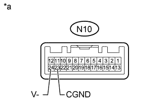
Text in Illustration *a Component without harness connected
(Navigation Receiver Assembly)
Disconnect the N10 navigation receiver assembly connector.
-
Measure the resistance according to the value(s) in the table below.
Standard Resistance Tester Connection Condition Specified Condition N10-23 (CGND) - Body ground Always Below 1 Ω N10-24 (V-) - Body ground Always Below 1 Ω
NG
REPLACE NAVIGATION RECEIVER ASSEMBLY Click here
OK
-
-
CHECK NAVIGATION RECEIVER ASSEMBLY
-
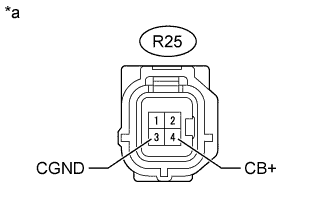
Text in Illustration *a Front view of wire harness connector
(to Rear Television Camera Assembly)
Disconnect the R25 rear television camera assembly connector.
-
Measure the voltage according to the value(s) in the table below.
Standard Voltage Tester Connection Switch Condition Specified Condition R25-4 (CB+) - R25-3 (CGND) Ignition switch ACC 5.5 to 7.05 V
NG
REPLACE NAVIGATION RECEIVER ASSEMBLY Click here
OK
-
-
CHECK REAR TELEVISION CAMERA ASSEMBLY
-
Using an oscilloscope, check the waveform.
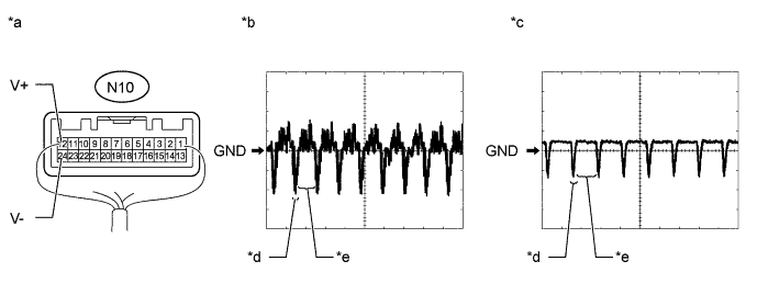
Text in Illustration *a Component with harness connected
(Navigation Receiver Assembly)
*b Waveform 1 *c Waveform 2 *d Synchronized Signal *e Video Waveform - - Measurement Condition Item Content Tester Connection N10-12 (V+) - N10-24 (V-) Tool Setting 0.2 V/DIV., 50 μs/DIV. Condition
-
Waveform 1: Ignition switch ON, shift lever in R
-
Waveform 2: Ignition switch ON, shift lever in R, screen blacked out by covering camera lens
OK Waveform is as shown in illustration. Tech Tips
The video waveform changes according to the image sent by the rear television camera assembly.
-
NG
REPLACE REAR TELEVISION CAMERA ASSEMBLY Click here
OK 
PROCEED TO NEXT SUSPECTED AREA SHOWN IN PROBLEM SYMPTOMS TABLE Click here
-