SHIFT AND SELECT LEVER SHAFT REASSEMBLY
PROCEDURE
INSTALL SELECT STOPPER BLOCK
Coat the select stopper block with gear oil.
-
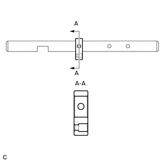
Install the select stopper block as shown in the illustration.
Note:Confirm the installation direction.
-
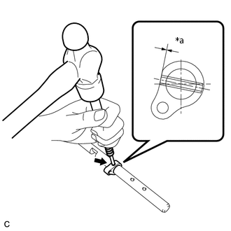
*a
Depth
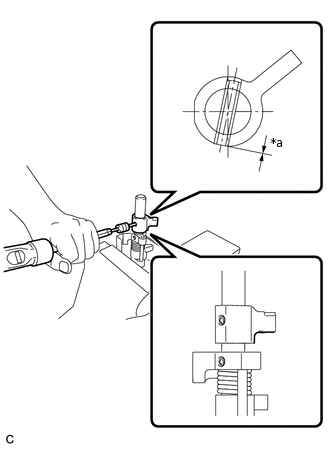
Using a 5 mm pin punch and a hammer, install the slotted spring pin to the shift and select lever shaft.
Driven in Depth
-0.2 to 0.8 mm (-0.00787 to 0.0315 in.)
INSTALL RELEASE HEAD STRAIGHT PIN
-
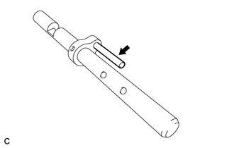
Install the release head straight pin to the select stopper block.
Coat the release head with gear oil.
-
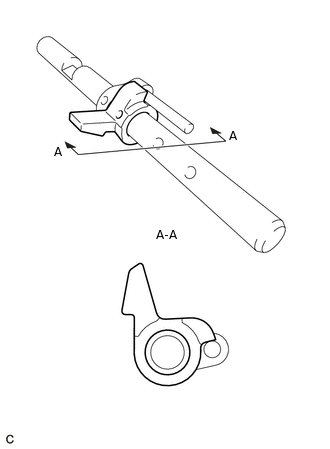
Install that the release head as shown in the illustration.
Note:Confirm the installation direction.
-
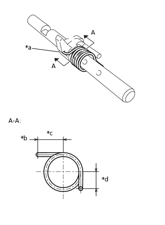
*a
Hook
*b
Hook Side
*c
14.5 to 15.5 mm (0.571 to 0.610 in.)
*d
8.3 to 9.3 mm (0.327 to 0.366 in.)
Install the release head torsion spring as shown in the illustration.
Note:Confirm the installation direction.
Coat the front inner shift lever with gear oil.
-
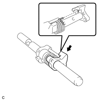
Install the front inner shift lever as shown in the illustration.
Note:Confirm the installation direction.
Tip:Insert the release head torsion spring to the installation hole of the front inner shift lever.
-
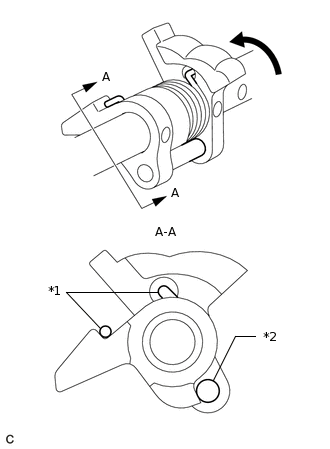
*1
Spring
*2
Straight Pin
Turn the front inner shift lever counterclockwise to align it with the installation surface of the straight pin, and install it.
Note:Confirm that the front inner shift lever is installed as shown in the illustration.
-
*a
Depth
Using a 5 mm pin punch and a hammer, install the slotted spring pin to the shift and select lever shaft.
Driven in Depth
-0.2 to 0.8 mm (-0.00787 to 0.0315 in.)
-
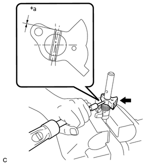
INSTALL INNER NO. 2 SHIFT LEVER
Coat the inner No. 2 shift lever with gear oil.
-
*a
Depth
Using a 5 mm pin punch and a hammer, install the inner No. 2 shift lever and slotted spring pin to the shift and select lever shaft.
Driven in Depth
0 to 0.6 mm (0 to 0.0236 in.)
Note:Confirm the installation direction.