ENGINE UNIT DISASSEMBLY
CAUTION / NOTICE / HINT
When replacing the injectors (including shuffling the injectors between the cylinders), common rail assembly, intake manifold or cylinder head sub-assembly, it is necessary to replace the injection pipes with new ones.
When replacing the fuel supply pump assembly, common rail assembly, intake manifold or cylinder head sub-assembly, it is necessary to replace the fuel inlet pipe with a new one.
PROCEDURE
REMOVE NO. 2 NOZZLE LEAKAGE PIPE
REMOVE NO. 1 NOZZLE LEAKAGE PIPE
REMOVE NO. 1 NOZZLE HOLDER CLAMP
REMOVE INJECTOR ASSEMBLY
REMOVE CAMSHAFT POSITION SENSOR
-
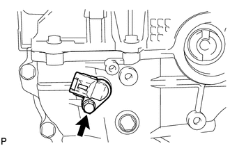
Remove the bolt and camshaft position sensor.
-
REMOVE CRANKSHAFT POSITION SENSOR
-
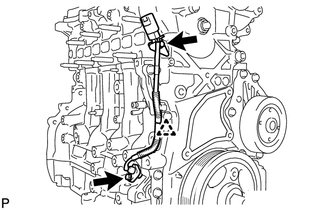
Remove the clip and disconnect the crankshaft position sensor harness.
Remove the 2 bolts and crankshaft position sensor.
-
REMOVE ENGINE COOLANT TEMPERATURE SENSOR
REMOVE ENGINE WATER PUMP ASSEMBLY
REMOVE ENGINE OIL PRESSURE SWITCH ASSEMBLY
REMOVE OIL COOLER ASSEMBLY
REMOVE NO. 1 OIL COOLER BRACKET
REMOVE ENGINE OIL LEVEL SENSOR
-
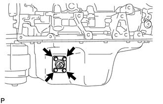
Remove the 4 bolts and engine oil level sensor.
-
REMOVE WATER INLET HOUSING
REMOVE OIL FILLER CAP SUB-ASSEMBLY
REMOVE CYLINDER HEAD COVER SUB-ASSEMBLY
REMOVE NO. 2 OIL PAN SUB-ASSEMBLY
REMOVE OIL FILTER ELEMENT
REMOVE OIL FILTER BRACKET
REMOVE OIL STRAINER SUB-ASSEMBLY
SET NO. 1 CYLINDER TO TDC / COMPRESSION
-
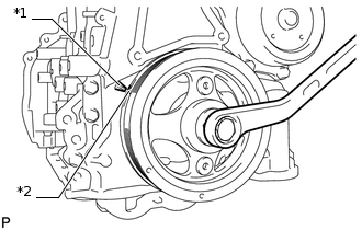
*1
Timing Pointer
*2
Timing Mark
Turn the crankshaft pulley clockwise to align the timing mark on the crankshaft pulley with the timing pointer of the timing chain cover sub-assembly.
-
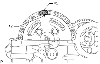
*1
Matchmark
*2
Timing Mark
Make sure that the timing mark of the camshaft timing sprocket is at the top.
Tip:If the timing mark is not at the top, turn the crankshaft pulley 1 revolution so that the timing mark is at the top (set the No. 1 cylinder to TDC/compression).
Put a matchmark on the timing chain plate that is aligned with the timing mark of the camshaft timing sprocket.
Tip:The timing chain has 2 yellow-colored plates. If either of them is aligned with the timing mark of the camshaft timing sprocket, this step can be omitted.
-
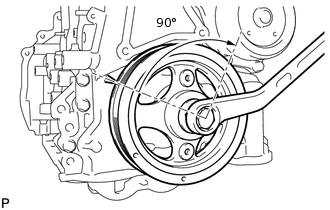
Turn the crankshaft pulley by approximately 90° in the direction of engine revolution from the point where the No. 1 cylinder is set to TDC/compression so that the lifted valve and piston do not contact each other when removing the camshaft.
-
REMOVE CRANKSHAFT PULLEY
-
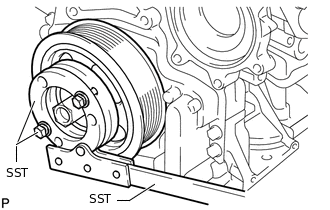
Using SST, loosen the crankshaft pulley bolt.
09213-58014
91551-80840
09330-00021
-
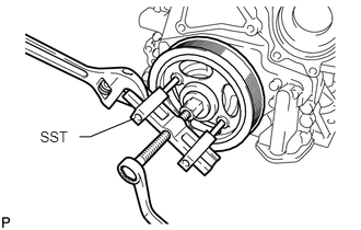
Using SST, remove the bolt and crankshaft pulley.
09950-50013
09951-05010
09952-05010
09953-05020
09954-05021
-
REMOVE TIMING CHAIN COVER SUB-ASSEMBLY
REMOVE FRONT CRANKSHAFT OIL SEAL
REMOVE NO. 1 CHAIN TENSIONER ASSEMBLY
-
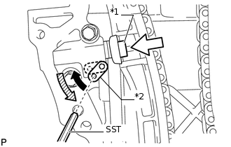
*1
Plunger
*2
Stopper Plate
Move the stopper plate upward to release the lock, and push the plunger deep into the No. 1 chain tensioner assembly.
Move the stopper plate downward to set the lock, and insert SST into the stopper plate hole.
09240-00020
09242-00200
-
Remove the 2 bolts and No. 1 chain tensioner assembly.
-
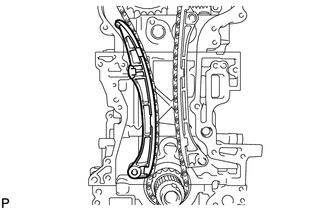
REMOVE CHAIN TENSIONER SLIPPER
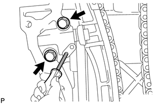
REMOVE NO. 1 CHAIN VIBRATION DAMPER
-
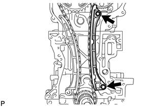
Remove the 2 bolts and No. 1 chain vibration damper.
-
REMOVE CAMSHAFT TIMING SPROCKET
-
Remove the 4 bolts from the camshaft timing sprocket while holding the hexagonal portion of the No. 2 camshaft with a wrench.
Remove the camshaft timing sprocket and chain sub-assembly.
-
REMOVE OIL PUMP DRIVE GEAR
-
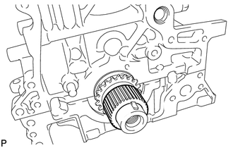
Remove the oil pump drive gear from the crankshaft.
-
REMOVE CRANKSHAFT TIMING SPROCKET
-
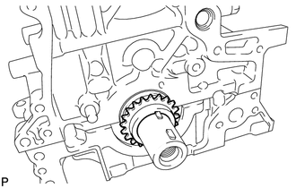
Remove the crankshaft timing sprocket from the crankshaft.
-
REMOVE CRANKSHAFT PULLEY SET CRANKSHAFT KEY
-
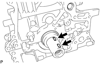
Remove the 2 crankshaft pulley set crankshaft keys from the crankshaft.
-
REMOVE CAMSHAFT
REMOVE NO. 1 VALVE ROCKER ARM SUB-ASSEMBLY
REMOVE VALVE LASH ADJUSTER ASSEMBLY
REMOVE CYLINDER HEAD SUB-ASSEMBLY
REMOVE CYLINDER HEAD GASKET
REMOVE REAR ENGINE OIL SEAL
REMOVE OIL BAFFLE PLATE
-
Remove the 2 bolts and oil baffle plate.
-
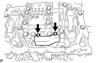
REMOVE ENGINE BALANCER ASSEMBLY
-
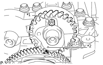
*1
Service Bolt
*2
Timing Mark
Align the timing marks (1 dot mark each) of the drive and driven gears by turning the crankshaft with a wrench.
Put matchmarks on the drive gear and driven gear.
Install a service bolt.
Recommended Service Bolt
Item
Specified Condition
Thread diameter
6 mm (0.236 in.)
Thread pitch
1 mm (0.0394 in.)
Bolt length
16 to 18 mm (0.630 to 0.709 in.)
1.5 N*m
15 kgf*cm
13 in.*lbf
Tip:When removing the balancer, make sure that the torsional spring force of the sub gear has been eliminated by the installation of the service bolt.
-
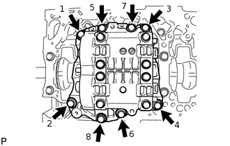
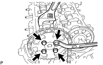
Uniformly loosen the 8 bolts in several steps, in the sequence shown in the illustration.
Remove the engine balancer assembly.
-
REMOVE CYLINDER BLOCK WATER DRAIN COCK SUB-ASSEMBLY
-
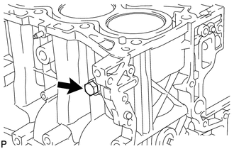
Remove the cylinder block water drain cock sub-assembly from the cylinder block sub-assembly.
-