ENTRY AND START SYSTEM(for Start Function) Power Source Mode does not Change to ON (IG)
| DTC Code | DTC Name |
|---|---|
| Power Source Mode does not Change to ON (IG) |
DESCRIPTION
When the engine switch is pushed with the key in the cabin, the power management control ECU receives signals to switch the power source mode.
WIRING DIAGRAM
Refer to "Power Source Mode does not Change to on (IG and ACC)" (Click here).
CAUTION / NOTICE / HINT
When using the intelligent tester with the engine switch off to troubleshoot: Connect the intelligent tester to the vehicle, and turn a courtesy light switch on and off at 1.5 second intervals until communication between the intelligent tester and vehicle begins.
Before performing the inspection, check that there are no problems related to the CAN communication system and LIN communication system.
Inspect the fuses for circuits related to this system before performing the following inspection procedure.
PROCEDURE
CHECK HARNESS AND CONNECTOR (BATTERY - POWER MANAGEMENT CONTROL ECU)
REPAIR OR REPLACE HARNESS OR CONNECTOR
CHECK HARNESS AND CONNECTOR (POWER MANAGEMENT CONTROL ECU - BODY GROUND)
REPAIR OR REPLACE HARNESS OR CONNECTOR
CHECK INSTRUMENT PANEL JUNCTION BLOCK ASSEMBLY (IG1 RELAY)
REPAIR OR REPLACE HARNESS OR CONNECTOR, OR REPLACE INSTRUMENT PANEL JUNCTION BLOCK ASSEMBLY (IG1 RELAY)Click here
INSPECT IG1 RELAY
REPAIR OR REPLACE HARNESS OR CONNECTOR, OR REPLACE INSTRUMENT PANEL JUNCTION BLOCK ASSEMBLY (IG1 RELAY)Click here
CHECK HARNESS AND CONNECTOR (POWER MANAGEMENT CONTROL ECU - BODY GROUND)
REPAIR OR REPLACE HARNESS OR CONNECTOR, OR REPLACE INSTRUMENT PANEL JUNCTION BLOCK ASSEMBLY (IG1 RELAY)Click here
CHECK POWER MANAGEMENT CONTROL ECU
Disconnect the H71 and H70 power management control ECU connectors.
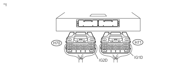
Table 1. Text in Illustration *1
Rear view of wire harness connector
(Power Management Control ECU)
-
-
Measure the resistance according to the value(s) in the table below.
Standard Resistance
Tester Connection
Condition
Specified Condition
H70-8 (IG2D) - Body ground
20°C (68°F)
255 to 387 Ω
H71-20 (IG1D) - Body ground
20°C (68°F)
152 to 203 Ω
Table 2. Result Result
Proceed to
OK
A
NG (for LHD)
B
NG (for RHD)
C
CHECK ENGINE SWITCH
END
REPAIR OR REPLACE HARNESS OR CONNECTOR (BATTERY - IG1 RELAY AND IG2 RELAY)
REPAIR OR REPLACE HARNESS OR CONNECTOR, OR REPLACE INSTRUMENT PANEL JUNCTION BLOCK ASSEMBLY (IG1 RELAY)
CHECK POWER MANAGEMENT CONTROL ECU
CHECK ENGINE SWITCH
END
REPAIR OR REPLACE HARNESS OR CONNECTOR (BATTERY - IG1 RELAY AND IG2 RELAY)