TIRE PRESSURE WARNING SYSTEM ECU Power Source Circuit
DESCRIPTION
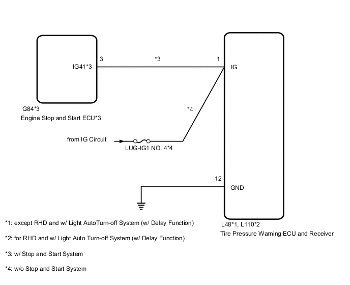
The IG circuit is the power source for the tire pressure warning ECU and receiver.
WIRING DIAGRAM
CAUTION / NOTICE / HINT
Note
-
When replacing the tire pressure warning ECU and receiver, first use the GTS to record all of the current IDs and registered tires with transmitters (4 or 5 tires) of the tire pressure warning valve and transmitter registered to the tire pressure warning ECU and receiver.
-
It is necessary to perform initialization after registration Click here of the transmitter IDs into the tire pressure warning ECU and receiver if the ECU has been replaced.
Tech Tips
w/o Stop and Start System:
Inspect the fuses for circuits related to this system before performing the following inspection procedure.
PROCEDURE
-
CHECK HARNESS AND CONNECTOR (IG TERMINAL)
-
Disconnect the L48*1 or L110*2 tire pressure warning ECU and receiver connector.
-
*1: except RHD and w/ Light Auto Turn-off System (w/ Delay Function)
-
*2: for RHD and w/ Light Auto Turn-off System (w/ Delay Function)
-
-
Measure the voltage according to the value(s) in the table below.
Standard Voltage except RHD and w/ Light Auto Turn-off System (w/ Delay Function) Tester Connection Condition Specified Condition L48-1 (IG) - Body ground Engine switch on (IG) 10 to 16 V Engine switch off Below 1 V for RHD and w/ Light Auto Turn-off System (w/ Delay Function) Tester Connection Condition Specified Condition L110-1 (IG) - Body ground Engine switch on (IG) 10 to 16 V Engine switch off Below 1 V Result Proceed to OK NG (w/ Stop and Start System) NG (w/o Stop and Start System)
NG (w/ Stop and Start System) 
INSPECT STOP AND START SYSTEM (BACKUP BOOST CONVERTER CIRCUIT) for 8GR-FKS: Click here
INSPECT STOP AND START SYSTEM (BACKUP BOOST CONVERTER CIRCUIT) for V35A-FTS: Click hereNG (w/o Stop and Start System)
REPAIR OR REPLACE HARNESS OR CONNECTOR
OK 
-
-
CHECK HARNESS AND CONNECTOR (GND TERMINAL)
-
Measure the resistance according to the value(s) in the table below.
Standard Resistance except RHD and w/ Light Auto Turn-off System (w/ Delay Function) Tester Connection Condition Specified Condition L48-12 (GND) - Body ground Always Below 1 Ω for RHD and w/ Light Auto Turn-off System (w/ Delay Function): Tester Connection Condition Specified Condition L110-12 (GND) - Body ground Always Below 1 Ω Result Proceed to OK NG
OK
REPLACE TIRE PRESSURE WARNING ECU AND RECEIVER except RHD and w/ Light Auto Turn-off System (w/ Delay Function): REPLACE TIRE PRESSURE WARNING ECU AND RECEIVER Click here
REPLACE TIRE PRESSURE WARNING ECU AND RECEIVER for RHD and w/ Light Auto Turn-off System (w/ Delay Function): REPLACE TIRE PRESSURE WARNING ECU AND RECEIVER Click hereNG
REPAIR OR REPLACE HARNESS OR CONNECTOR
-