SHIFT LEVER REMOVAL
PROCEDURE
-
PRECAUTION
Note
-
If the shift lock control unit assembly is to be replaced with a new one, it is necessary to clear the learned shift sensor voltage values by disconnecting and reconnecting the cable of the negative (-) auxiliary battery terminal.
-
After turning the power switch off, waiting time may be required before disconnecting the cable from the negative (-) auxiliary battery terminal. Therefore, make sure to read the disconnecting the cable from the negative (-) auxiliary battery terminal notices before proceeding with work Click here.
-
-
REMOVE DECK BOARD ASSEMBLY
-
REMOVE NO. 1 DECK BOARD
-
REMOVE NO. 2 DECK BOARD
-
REMOVE REAR DECK FLOOR BOX
-
REMOVE DECK FLOOR BOX RH
-
DISCONNECT CABLE FROM NEGATIVE AUXILIARY BATTERY TERMINAL
Note
When disconnecting the cable, some systems need to be initialized after the cable is reconnected Click here.
-
REMOVE SHIFT LEVER KNOB
-
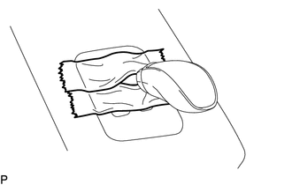
Apply protective tape around the shift lock control unit assembly.
Note
As adhesive residue may fall when removing the shift lever knob, apply protective tape.
-
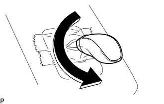
Turn the shift lever knob in the direction of the arrow in the illustration to remove it.
-
-
REMOVE INTEGRATION CONTROL AND PANEL
-
REMOVE UPPER INSTRUMENT PANEL FINISH PANEL
-
REMOVE CONSOLE BOX ASSEMBLY
-
REMOVE LOWER INSTRUMENT PANEL FINISH PANEL SUB-ASSEMBLY
-
REMOVE SHIFT LOCK CONTROL UNIT ASSEMBLY
-
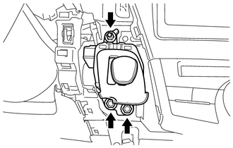
Remove the 3 nuts and separate the shift lock control unit assembly.
-
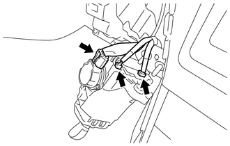
Disconnect the 3 connectors and remove the shift lock control unit assembly.
-