INTEGRATION RELAY(for Engine Room Side) INSTALLATION
PROCEDURE
-
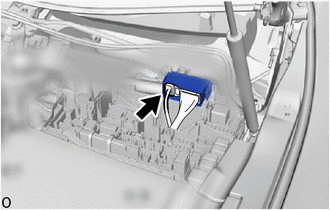
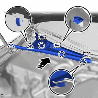
INSTALL NO. 1 SEMICONDUCTOR POWER INTEGRATION ECU (for LHD)
-
Attach the claw and connect the lever connector.
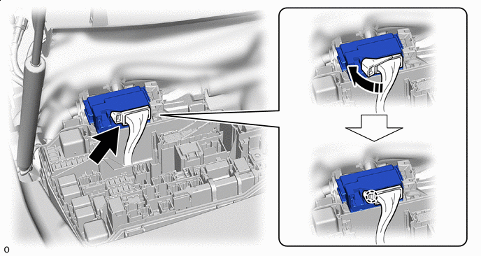

Rotate in this Direction - - Note
-
Make sure the connector terminal is free from oil and grease.
-
Do not subject the No. 1 semiconductor power integration ECU to any impact.
-
Do not use a No. 1 semiconductor power integration ECU that has been dropped.
-
Do not disassemble the No. 1 semiconductor power integration ECU.
-
Make sure the lever connector is securely connected.
-
-
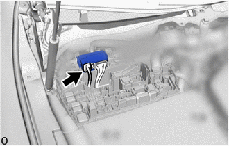
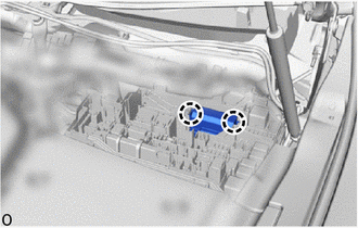
Connect the power source connector.
Note
-
Make sure the connector terminal is free from oil and grease.
-
Do not subject the No. 1 semiconductor power integration ECU to any impact.
-
Do not use a No. 1 semiconductor power integration ECU that has been dropped.
-
Do not disassemble the No. 1 semiconductor power integration ECU.
-
-
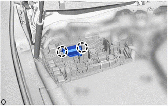
Attach the claw to install the No. 1 semiconductor power integration ECU.
Note
-
Make sure the connector terminal is free from oil and grease.
-
Do not subject the No. 1 semiconductor power integration ECU to any impact.
-
Do not use a No. 1 semiconductor power integration ECU that has been dropped.
-
Do not disassemble the No. 1 semiconductor power integration ECU.
-
-
-
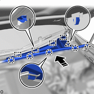
INSTALL NO. 1 SEMICONDUCTOR POWER INTEGRATION ECU (for RHD)
-
Attach the claw and connect the lever connector.
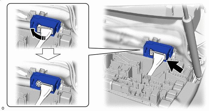
Rotate in this Direction - - Note
-
Make sure the connector terminal is free from oil and grease.
-
Do not subject the No. 1 semiconductor power integration ECU to any impact.
-
Do not use a No. 1 semiconductor power integration ECU that has been dropped.
-
Do not disassemble the No. 1 semiconductor power integration ECU.
-
Make sure the lever connector is securely connected.
-
-
Connect the power source connector.
Note
-
Make sure the connector terminal is free from oil and grease.
-
Do not subject the No. 1 semiconductor power integration ECU to any impact.
-
Do not use a No. 1 semiconductor power integration ECU that has been dropped.
-
Do not disassemble the No. 1 semiconductor power integration ECU.
-
-
Attach the claw to install the No. 1 semiconductor power integration ECU.
Note
-
Make sure the connector terminal is free from oil and grease.
-
Do not subject the No. 1 semiconductor power integration ECU to any impact.
-
Do not use a No. 1 semiconductor power integration ECU that has been dropped.
-
Do not disassemble the No. 1 semiconductor power integration ECU.
-
-
-
INSTALL NO. 1 RELAY BLOCK COVER (for LHD)
-
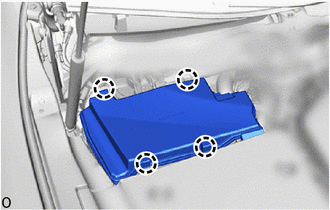
Attach the claw to install the No. 1 relay block cover.
-
-
INSTALL NO. 1 RELAY BLOCK COVER (for RHD)
-
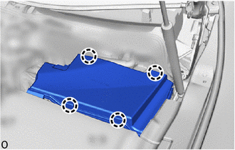
Attach the claw to install the No. 1 relay block cover.
-
-
INSTALL CENTER COWL TOP VENTILATOR LOUVER (for LHD)
-
Install in this Direction Attach the guide, claw, clip and install the center cowl top ventilator louver.
-
-
INSTALL CENTER COWL TOP VENTILATOR LOUVER (for RHD)
-
Install in this Direction Attach the guide, claw, clip and install the center cowl top ventilator louver.
-
-
INSTALL V-BANK COVER SUB-ASSEMBLY (for 8GR-FKS)
-
INSTALL V-BANK COVER SUB-ASSEMBLY (for V35A-FTS)
-
CONNECT CABLE TO NEGATIVE BATTERY TERMINAL
-
for 8GR-FKS:
-
for V35A-FTS:
-
-
INSTALL LUGGAGE COMPARTMENT MAT SUB-ASSEMBLY