DIFFERENTIAL SYSTEM
-
CONSTRUCTION
-
The electronic differential lock case sub-assembly consists of a case, side gear, return spring, cam ring, position plate, plunger assembly and coil assembly.
-
The side gear RH and the cam ring have been provided with teeth to function as a dog clutch.
-
The 4 wheel drive control ECU supplies current to the coil assembly, which generates magnetic flux and operates the plunger assembly to engage the dog clutch, locking the differential.
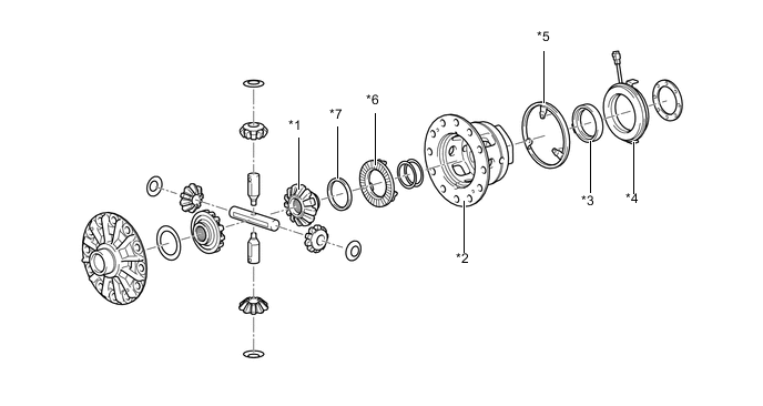
*1 Side Gear RH *2 Case *3 Plunger Assembly *4 Coil Assembly *5 Position Plate *6 Cam Ring *7 Return Spring - -
-
-
OPERATION
-
Power Flow
-
Normal Driving (Rear Differential Lock Not Engaged)
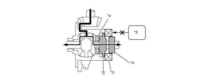
*1 Side Gear RH *2 Cam Ring *3 Coil Assembly (Current Not Supplied) *4 Plunger Assembly *5 4 Wheel Drive Control ECU - - *a Dog Clutch (Not Engaged) - - 
Power Flow - - -
Rear Wheel LH Spinning (Rear Differential Not Engaged)
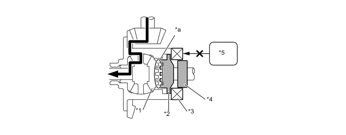
*1 Side Gear RH *2 Cam Ring *3 Coil Assembly (Current Not Supplied) *4 Plunger Assembly *5 4 Wheel Drive Control ECU - - *a Dog Clutch (Not Engaged) - - Power Flow - - -
Rear Differential Lock Engaged
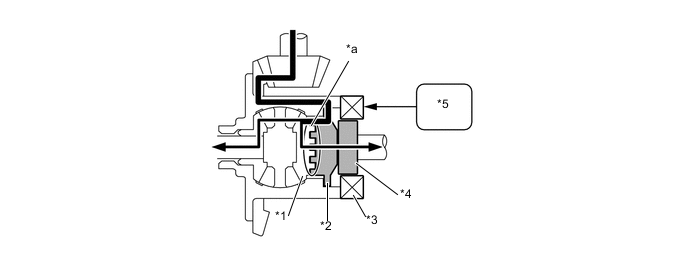
*1 Side Gear RH *2 Cam Ring *3 Coil Assembly (Current Supplied) *4 Plunger Assembly *5 4 Wheel Drive Control ECU - - *a Dog Clutch (Engaged) - - Power Flow - -
-
-