STEERING GEAR INSTALLATION
PROCEDURE
INSTALL TIE ROD END SUB-ASSEMBLY LH
-
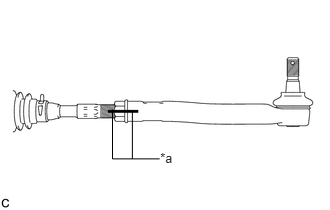
Install the lock nut and tie rod end sub-assembly to the steering gear so that the matchmarks align.
Table 1. Text in Illustration *a
Matchmark
Tip:After adjusting toe-in, tighten the lock nut to the specified torque.
-
INSTALL TIE ROD END SUB-ASSEMBLY RH
Tip:Use the same procedures described for the LH side.
INSTALL STEERING GEAR ASSEMBLY
-
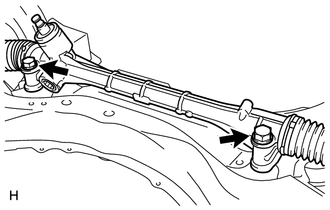
Install the steering gear to the front suspension crossmember with the 2 bolts and 2 nuts.
110 N*m
1397 kgf*cm
101 ft.*lbf
Note:Make sure to tighten the bolts starting from the left side of the vehicle.
Because the nut has its own stopper, do not turn the nut. Tighten the bolt with the nut fixed in place.
-
INSTALL STEERING INTERMEDIATE SHAFT
-
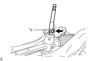
Align the matchmarks and install the steering intermediate shaft to the steering gear.
Table 2. Text in Illustration *a
Matchmark
Install a new bolt.
35 N*m
357 kgf*cm
26 ft.*lbf
-
INSTALL NO. 1 STEERING COLUMN HOLE COVER SUB-ASSEMBLY
-
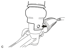
Align the round hole in the No. 1 steering column hole cover sub-assembly with the protrusion of the steering gear and install the cover.
-
INSTALL STEERING COLUMN HOLE SHIELD (w/ Steering Column Hole Shield)
-
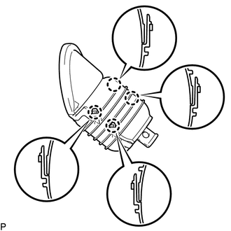
Engage the 4 claws to install the steering column hole shield to the No. 1 steering column hole cover .
-
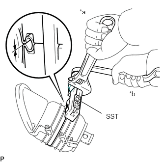
*a
Hold
*b
Turn
Using SST, install a new clamp on top of the steering column hole shield as shown in the illustration.
09521-24010
-
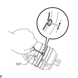
Using SST, measure the clearance.
09240-00020
Clearance
0.5 to 1.5 mm (0.0197 to 0.0590 in.)
-
INSTALL FRONT SUSPENSION CROSSMEMBER SUB-ASSEMBLY
INSTALL FRONT SUSPENSION MEMBER REAR BRACE LH
INSTALL FRONT SUSPENSION MEMBER REAR BRACE RH
CONNECT TIE ROD END SUB-ASSEMBLY LH
-
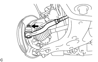
Connect the tie rod end to the steering knuckle with the nut.
49 N*m
500 kgf*cm
36 ft.*lbf
Note:Tighten the nut up to an additional 60° if the holes for the cotter pin are not aligned.
Install a new cotter pin.
-
CONNECT TIE ROD END SUB-ASSEMBLY RH
Tip:Use the same procedures described for the LH side.
INSTALL FRONT STABILIZER LINK ASSEMBLY LH
INSTALL FRONT STABILIZER LINK ASSEMBLY RH
Tip:Use the same procedures described for the LH side.
INSTALL FRONT SUSPENSION MEMBER REINFORCEMENT LH
INSTALL FRONT SUSPENSION MEMBER REINFORCEMENT RH
INSTALL REAR ENGINE UNDER COVER LH
INSTALL REAR ENGINE UNDER COVER RH
INSTALL CENTER NO. 4 ENGINE UNDER COVER (for 1ZR-FAE, 2ZR-FAE)
INSTALL NO. 2 ENGINE UNDER COVER
INSTALL NO. 1 ENGINE UNDER COVER (for 1ZR-FAE, 2ZR-FAE)
INSTALL NO. 1 ENGINE UNDER COVER (for 1WW)
CONNECT NO. 1 STEERING COLUMN HOLE COVER SUB-ASSEMBLY
-
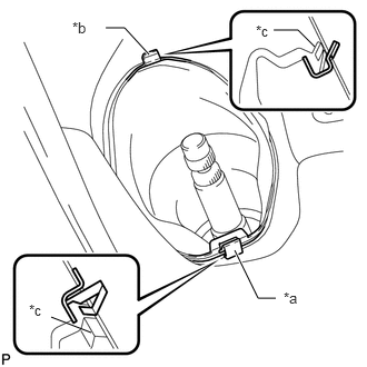
Attach clip B to the body and install the No. 1 steering column hole cover to the body with clip A.
Table 3. Text in Illustration *a
Clip A
*b
Clip B
*c
Lip
Note:Make sure that the lip of the No. 1 steering column hole cover is not damaged.
-
CONNECT NO. 2 STEERING INTERMEDIATE SHAFT ASSEMBLY
INSTALL COLUMN HOLE COVER SILENCER SHEET
INSTALL FRONT WHEELS
103 N*m
1050 kgf*cm
76 ft.*lbf
ADJUST FRONT WHEEL ALIGNMENT
Adjust the front wheel alignment (Click here).