INTAKE MANIFOLD (w/o EGR System) REMOVAL
Note
-
When replacing the injectors (including shuffling the injectors between the cylinders), common rail or cylinder head, it is necessary to replace the injection pipes with new ones.
-
When replacing the fuel supply pump, common rail, cylinder block, cylinder head, cylinder head gasket or timing gear case, it is necessary to replace the fuel inlet pipe with a new one.
-
After removing the injection pipes, clean them with a brush and compressed air.
-
DISCONNECT CABLE FROM NEGATIVE BATTERY TERMINAL
CAUTION:
Wait at least 90 seconds after disconnecting the cable from the negative (-) battery terminal to prevent airbag and seat belt pretensioner activation.
Note
When disconnecting the cable, some systems need to be initialized after the cable is reconnected Click here.
-
REMOVE NO. 1 ENGINE COVER SUB-ASSEMBLY
-
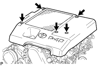
Remove the 3 bolts, 2 nuts and cover.
-
-
REMOVE INTERCOOLER ASSEMBLY
-
REMOVE DIESEL THROTTLE BODY ASSEMBLY
-
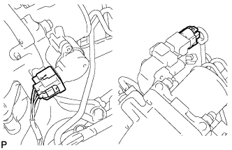
Disconnect the 2 connectors.
-
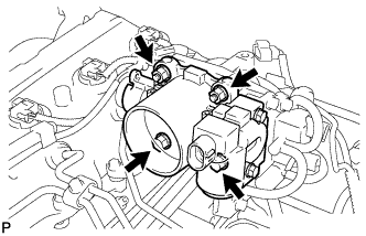
Remove the 2 bolts, 2 nuts, throttle body and gasket.
-
-
REMOVE VACUUM SWITCHING VALVE BRACKET
-
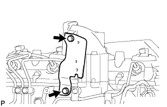
Remove the 2 bolts and vacuum switching valve bracket.
-
-
REMOVE NO. 2 INTAKE AIR CONNECTOR BRACKET
-
Remove the 3 bolts and No. 2 intake air connector bracket.
-
-
REMOVE INTAKE AIR CONNECTOR
-
Remove the 2 nuts, bolt, intake air connector and gasket.
-
-
REMOVE MANIFOLD STAY
-
Remove the 2 bolts and stay.
-
-
REMOVE ENGINE OIL LEVEL DIPSTICK GUIDE
-
Remove the engine oil level dipstick.
-
Remove the bolt and injection pipe clamp.
-
Remove the bolt and engine oil level dipstick guide.
-
Remove the O-ring from the engine oil level dipstick guide.
-
-
REMOVE NO. 1, NO. 2 AND NO. 3 INJECTION PIPE SUB-ASSEMBLY
Note
-
After removing the fuel pipe, cover the outlets on the common rail with tape to keep out foreign matter.
-
After removing the fuel pipe, put it in a plastic bag to prevent foreign matter from contaminating its injector inlet.
-
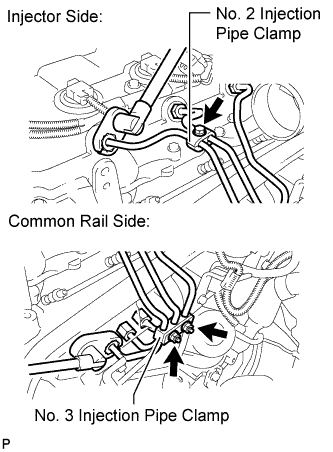
Remove the bolt and No. 2 injection pipe clamp.
-
Remove the 2 nuts and No. 3 injection pipe clamp.
-
Using a 17 mm union nut wrench, loosen the union nuts and remove the No. 1, No. 2 and No. 3 injection pipes.
-
-
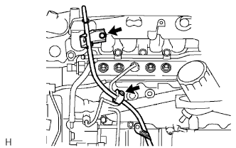
REMOVE NO. 4 INJECTION PIPE SUB-ASSEMBLY
-
Remove the 2 bolts and disconnect the 2 injection pipe clamps.
Note
If an injection pipe clamp is removed from the No. 4 injection pipe, replace the injection clamp with a new one.
-
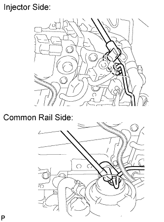
Using a 17 mm union nut wrench, loosen the union nuts and remove the No. 4 injection pipe.
-
-
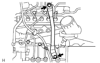
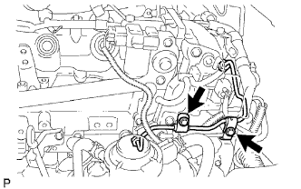
REMOVE NO. 2 NOZZLE LEAKAGE PIPE ASSEMBLY
-
Disconnect the 3 fuel hoses.
-
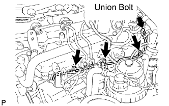
Remove the union bolt, 3 bolts, No. 2 nozzle leakage pipe and gasket.
-
-
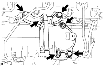
REMOVE INTAKE MANIFOLD
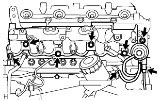
-
Disconnect the vacuum hose.
-
Disconnect the VSV connector.
-
Remove the 2 nuts, 4 bolts, intake manifold and gasket.
-