BRAKE CONTROL SYSTEM
-
CONSTRUCTION
-
The brake actuator assembly consists of hydraulic control and hydraulic power source portions.
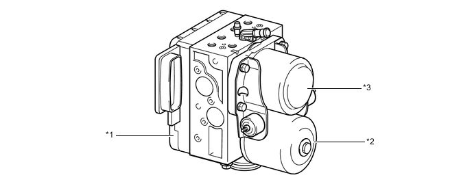
*1 Hydraulic Control Portion *2 Hydraulic Power Source Portion
- Pump and Pump Motor
*3 Hydraulic Power Source Portion
- Accumulator
- - Function of Brake Actuator Assembly Components Component Function Hydraulic Control Portion Master Cylinder Pressure Sensor The master cylinder pressure sensor converts the fluid pressure generated by the master cylinder into electrical signals and transmits them to the skid control ECU assembly. Accordingly, the skid control ECU assembly determines the braking force required by the driver. Relief Valve This valve returns the brake fluid to the brake master cylinder reservoir assembly to prevent excessive pressure if the pump motor operates continuously due to a malfunction of the accumulator pressure sensor. Accumulator Pressure Sensor This sensor constantly monitors the brake fluid pressure in the accumulator and transmits a signal to the skid control ECU assembly. Accordingly, the skid control ECU assembly controls the pump motor. Master Cylinder Cut Solenoid Valve (Switching Solenoid Valve)
-
When the brake pedal is depressed, this valve cuts the hydraulic passage between the brake master cylinder sub-assembly and the wheel cylinder.
-
When the brake pedal is not depressed or a failure occurs in the hydraulic power source portion, the valves open to maintain the hydraulic passage to the front wheel cylinders and ensure braking.
-
When a failure occurs, a greater effort than normal is required to depress the brake pedal.
Pressure Application Solenoid Valve (Linear Solenoid Valve) This valve is controlled by the skid control ECU assembly, regulating the fluid pressure from the accumulator in order to amplify the fluid pressure to the wheel cylinders. Pressure Reduction Solenoid Valve (Linear Solenoid Valve) This valve is controlled by the skid control ECU assembly, regulating the fluid pressure in order to reduce the fluid pressure to the wheel cylinders. Wheel Cylinder Pressure Sensor This sensor detects the fluid pressure that acts on their respective wheel cylinders and transmits the pressure to the skid control ECU assembly to provide feedback. Accordingly, the skid control ECU assembly can monitor the fluid pressure of the wheel cylinders and control the pressure application solenoid valves and the pressure reduction solenoid valves, in order to achieve the optimal wheel cylinder pressures. Hydraulic Power Source Portion Pump and Pump Motor Draw up the brake fluid from the brake master cylinder reservoir assembly and provides high hydraulic pressure to the accumulator. Accumulator Stores the hydraulic pressure that was generated by the pump. The accumulator is filled with high pressure nitrogen gas. -
-
A plunger type pump is used. This pump is operated by rotation of the camshaft driven by the pump motor, and then supplies high hydraulic pressure to the accumulator.
-
The high pressure nitrogen gas is charged and sealed in the accumulator. A metallic bellows-formed tube is used, in order to enhance the gastight performance of the accumulator.
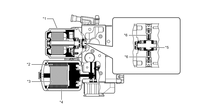
*1 Pump Motor *2 Bellows-formed *3 High Pressure Nitrogen Gas *4 Accumulator *5 Camshaft *6 Pump -
2 master cylinder pressure sensors, 4 wheel cylinder pressure sensors, an accumulator pressure sensor, 2 master cylinder cut solenoid valves, 4 pressure application solenoid valves and 4 pressure reduction solenoid valves are installed in the hydraulic control portion.
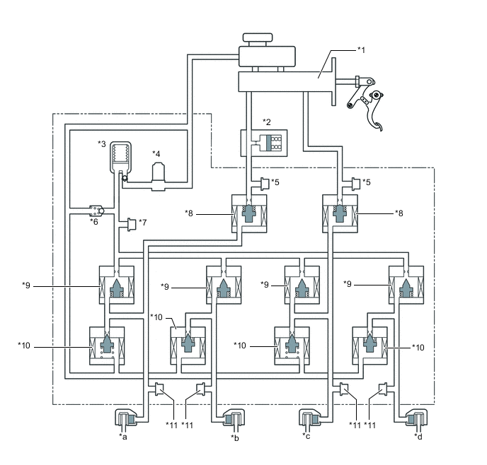
*1 Brake Master Cylinder Sub-assembly *2 Brake Stroke Simulator Cylinder Sub-assembly *3 Accumulator *4 Pump Motor *5 Master Cylinder Pressure Sensor *6 Relief Valve *7 Accumulator Pressure Sensor *8 Master Cylinder Cut Solenoid Valve (Switching Solenoid Valve) *9 Pressure Application Solenoid Valve (Linear Solenoid Valve) *10 Pressure Reduction Solenoid Valve (Linear Solenoid Valve) *11 Wheel Cylinder Pressure Sensor - - *a Front Brake LH *b Rear Brake RH *c Front Brake RH *d Rear Brake LH -
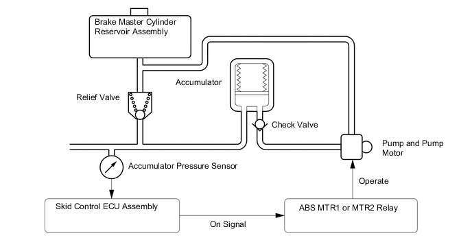
The brake fluid that is discharged by the pump passes through the check valve and is stored in the accumulator. The hydraulic pressure that is stored in the accumulator is used for providing the hydraulic pressure that is needed for normal braking and for operating the brake control.
-
The pump motor is activated upon receipt of signals from the skid control ECU assembly to turn on the ABS MTR1 and ABS MTR2 relays.
-
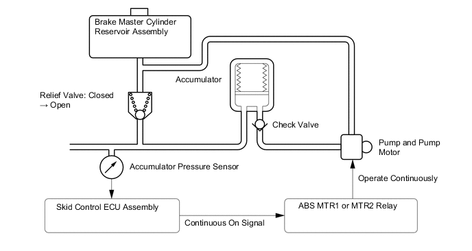
The accumulator pressure sensor constantly monitors the pressure in the accumulator and transmits it to the skid control ECU assembly. If the accumulator pressure drops below the set pressure, the skid control ECU assembly sends an activation signal to the motor relay in order to actuate the pump motor until the pressure in the accumulator reaches the set pressure.
-
If the pump and the pump motor continue to operate unintendedly, such as due to the failure of the accumulator pressure sensor, a high level of pressure would be created in the accumulator. At this time, the relief valve will open to return the brake fluid to the reservoir tank, to limit the accumulator pressure.
-
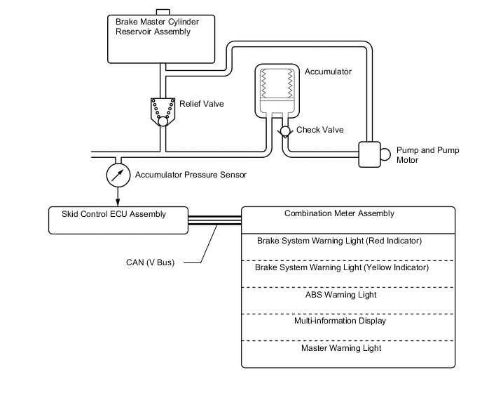
If the accumulator pressure drops abnormally to a level below the pressure set at the ECU, the skid control ECU assembly illuminates the brake system warning light (red indicator), brake system warning light (yellow indicator), ABS warning light and master warning light. Then, a warning message appears on the multi-information display.
-