TIRE PRESSURE WARNING SYSTEM, Diagnostic DTC:C2179
| DTC Code | DTC Name |
|---|---|
| C2179 | Tire Pressure Monitor ECU Communication Stop |
DESCRIPTION
The main body ECU (multiplex network body ECU) sends signals to the tire pressure warning ECU and receiver via a direct line.
| DTC No. | Detection Item | DTC Detection Condition | Trouble Area | Note |
|---|---|---|---|---|
| C2179 | Tire Pressure Monitor ECU Communication Stop | Communication between the main body ECU (multiplex network body ECU) and tire pressure warning ECU and receiver is interrupted for 10 seconds or more. |
|
- |
WIRING DIAGRAM
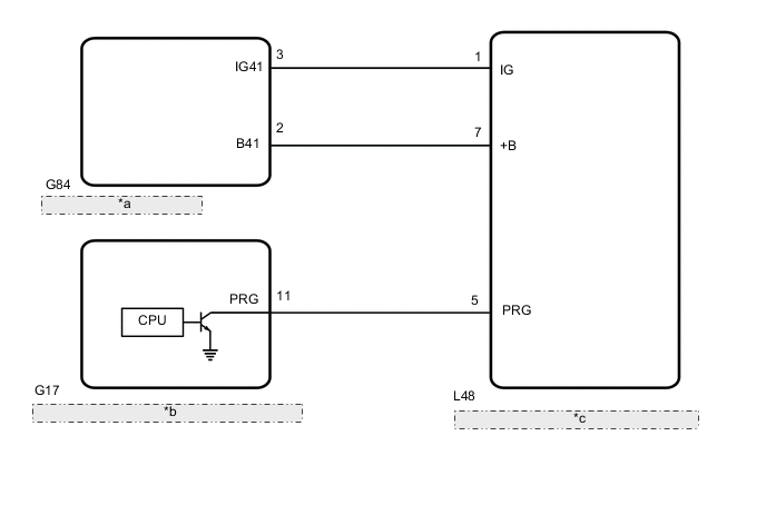
| *a | Engine Stop and Start ECU |
| *b | Main body ECU (Multiplex network body ECU) |
| *c | Tire Pressure Warning ECU and Receiver |
CAUTION / NOTICE / HINT
Note
-
When replacing the tire pressure warning ECU and receiver, first use the GTS to record all of the current IDs and registered tires with transmitters (4 or 5 tires) of the tire pressure warning valve and transmitter registered to the tire pressure warning ECU and receiver.
-
It is necessary to perform initialization after registration Click here of the transmitter IDs into the tire pressure warning ECU and receiver after the ECU has been replaced.
-
Before replacing the main body ECU (multiplex network body ECU), refer to Service Bulletin.
PROCEDURE
-
INSPECT MAIN BODY ECU (MULTIPLEX NETWORK BODY ECU) (OUTPUT WAVEFORM)
-
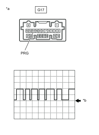
*a Component with harness connected
(Main Body ECU (Multiplex Network Body ECU))
*b GND Using an oscilloscope, check the waveform.
Note
With the connector connected, check from the backside of the connector.
Standard Voltage Tester Connection Tool Setting Range Condition Specified Condition G17-11 (PRG) - Body ground 5 V/DIV.5 ms./DIV. Engine switch on (IG) Waveform generation Result Result Proceed to Waveform is as shown in the illustration. (Waveform alternates between 9.8 V or higher and 1.2 V or less) A Waveform does not change from 9.8 V or higher B Waveform does not change from 1.2 V or less C
A 
REPLACE TIRE PRESSURE WARNING ECU AND RECEIVER Click here
B
REPLACE MAIN BODY ECU (MULTIPLEX NETWORK BODY ECU) Click here
C 
-
-
CHECK TERMINAL VOLTAGE (TIRE PRESSURE WARNING ECU AND RECEIVER OUTPUT)
-
Disconnect the G17 main body ECU (multiplex network body ECU) connector.
-
Measure the voltage according to the value(s) in the table below.
Standard Voltage Tester Connection Condition Specified Condition G17-11 (PRG) - Body ground Engine switch on (IG) 9.8 V or higher Result Proceed to OK NG
OK
REPLACE MAIN BODY ECU (MULTIPLEX NETWORK BODY ECU) Click here
NG
-
-
CHECK HARNESS AND CONNECTOR (TIRE PRESSURE WARNING ECU AND RECEIVER - MAIN BODY ECU (MULTIPLEX NETWORK BODY ECU))
-
Turn the engine switch off.
-
Disconnect the L48 tire pressure warning ECU and receiver connector.
-
Measure the resistance according to the value(s) in the table below.
Standard Resistance Tester Connection Condition Specified Condition L48-5 (PRG) - G17-11 (PRG) Always Below 1 Ω L48-5 (PRG) or G17-11 (PRG) - Body ground Always 10 kΩ or higher Result Proceed to OK NG
NG
REPAIR OR REPLACE HARNESS OR CONNECTOR
OK
-
-
CHECK HARNESS AND CONNECTOR (POWER SUPPLY - TIRE PRESSURE WARNING ECU AND RECEIVER)
-
Measure the voltage according to the value(s) in the table below.
Standard Voltage Tester Connection Condition Specified Condition L48-7 (+B) - Body ground Always 10 to 16 V L48-1 (IG) - Body ground Engine switch on (IG) 10 to 16 V Result Proceed to OK NG
OK
REPLACE TIRE PRESSURE WARNING ECU AND RECEIVER Click here
NG
INSPECT STOP AND START SYSTEM (BACKUP BOOST CONVERTER CIRCUIT) Click here
-