ENGINE UNIT INSTALLATION
PROCEDURE
INSTALL IGNITION COIL ASSEMBLY
INSTALL SENSOR WIRE
Install the sensor wire with the bolt.
21 N*m
214 kgf*cm
15 ft.*lbf
Connect the knock control sensor connector.
INSTALL INJECTOR VIBRATION INSULATOR
INSTALL FUEL DELIVERY PIPE
INSTALL INTAKE MANIFOLD
Install a new No. 1 intake manifold to head gasket to the intake manifold.
Temporarily install the intake manifold with the 6 bolts.
-
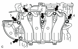
Tighten the 6 bolts in the order shown in the illustration.
28 N*m
286 kgf*cm
21 ft.*lbf
Connect the purge line hose to the intake manifold, and slide the clamp to secure the hose.
Connect the No. 2 PCV hose to the intake manifold, and slide the clamp to secure the hose.
INSTALL WATER INLET HOUSING
-
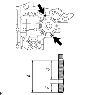
*a
34 mm (1.34 in.)
*b
21 mm (0.827 in.)
*c
9.0 mm (0.354 in.)
Using an E6 "TORX" socket wrench, install the 2 stud bolts to the water inlet housing.
4.4 N*m
45 kgf*cm
39 in.*lbf
Note:If a stud bolt is deformed or its threads are damaged, replace it.
-
*a
Bolt
*b
Nut
Install a new gasket and water inlet housing with the 3 bolts and nut.
43 N*m
438 kgf*cm
32 ft.*lbf
-
INSTALL OIL COOLER ASSEMBLY (w/ Oil Cooler)
INSTALL THERMOSTAT
INSTALL WATER INLET
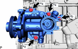
INSTALL ENGINE WATER PUMP ASSEMBLY
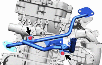
INSTALL NO. 3 WATER BY-PASS PIPE (w/o EGR System)
Install the No. 3 water by-pass pipe with the 2 bolts.
21 N*m
214 kgf*cm
15 ft.*lbf
TEMPORARILY INSTALL NO. 1 EGR PIPE (w/ EGR System)
-
Temporarily install the No. 1 EGR pipe with the 2 bolts.
-
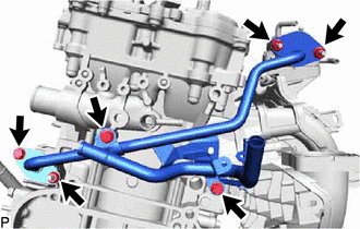
INSTALL NO. 1 WATER BY-PASS HOSE (w/ EGR System)
Install the No. 1 water by-pass hose to the cylinder block, and slide the hose clamp to secure the hose.
INSTALL NO. 3 WATER BY-PASS HOSE
Install the No. 3 water by-pass hose, and slide the hose clamp to secure the hose.
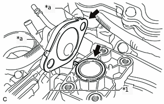
TEMPORARILY INSTALL EGR VALVE ASSEMBLY (w/ EGR System)
-
*1
Gasket
*a
Claw
Install 2 new gaskets to the No. 1 EGR pipe and intake manifold.
Note:Make sure that the gasket is installed in the correct direction.
-
Temporarily install the No. 1 EGR valve to the intake manifold with the 3 bolts.
Temporarily connect the No. 1 EGR pipe to the EGR valve assembly with the 2 nuts.
-
INSTALL NO. 1 WATER BY-PASS PIPE (w/o EGR System)
-
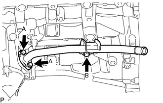
Temporarily install a new gasket and No. 1 water by-pass pipe with the 3 bolts.
Tighten the 2 bolts labeled A, and then tighten bolt B.
for bolt A
10 N*m
102 kgf*cm
7 ft.*lbf
for bolt B
21 N*m
214 kgf*cm
15 ft.*lbf
-
INSTALL NO. 5 WATER BY-PASS HOSE (w/o EGR System)
Install the No. 5 water by-pass hose to the water by-pass pipe and No. 3 water by-pass pipe, and slide the 2 hose clamps to secure the hose.
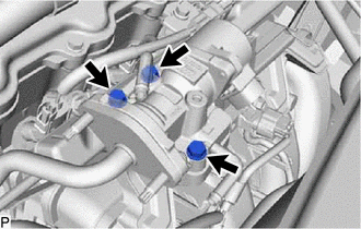
TEMPORARILY INSTALL EGR COOLER ASSEMBLY (w/ EGR System)
Install a new gasket to the No. 1 EGR pipe.
Note:Make sure that the gasket is installed in the correct direction.
-
*a
Claw
Temporarily install the EGR cooler assembly with the nut and bolt.
Tip:The nut and bolt can be installed to either side depending on the position of the stud bolt.
Connect the No. 5 water by-pass hose to the EGR cooler assembly, and slide the hose clamp to secure the hose.
Temporarily connect the No. 1 EGR pipe to the EGR cooler assembly with the bolt and nut.
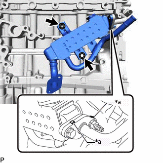
INSTALL WATER BY-PASS PIPE (w/ EGR System)
Install 2 new gaskets and the water by-pass pipe with the 4 bolts.
10 N*m
102 kgf*cm
7 ft.*lbf
TIGHTEN NO. 1 EGR PIPE (w/ EGR System)
-
Tighten the 3 bolts and 3 nuts.
21 N*m
214 kgf*cm
15 ft.*lbf
-
TIGHTEN EGR COOLER ASSEMBLY (w/ EGR System)
Tighten the bolt and nut.
21 N*m
214 kgf*cm
15 ft.*lbf
TIGHTEN EGR VALVE ASSEMBLY (w/ EGR System)
Tighten the 3 bolts.
10 N*m
102 kgf*cm
7 ft.*lbf
-
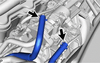
Connect the No. 1 water by-pass hose and No. 2 water by-pass hose to the EGR valve assembly, and slide the 2 clamps to secure the hose.
INSTALL THROTTLE WITH MOTOR BODY ASSEMBLY
INSTALL EXHAUST MANIFOLD CONVERTER SUB-ASSEMBLY
INSTALL MANIFOLD STAY
INSTALL NO. 2 MANIFOLD STAY
INSTALL NO. 2 EGR PIPE (w/ EGR System)
INSTALL NO. 1 EXHAUST MANIFOLD HEAT INSULATOR
INSTALL NO. 1 COMPRESSOR MOUNTING BRACKET
Install the No. 1 compressor mounting bracket with the 4 bolts.
24.5 N*m
250 kgf*cm
18 ft.*lbf
INSTALL COMPRESSOR ASSEMBLY WITH MOTOR
INSTALL V-RIBBED BELT TENSIONER ASSEMBLY
Install the V-ribbed belt tensioner assembly with the bolt.
21 N*m
214 kgf*cm
15 ft.*lbf
INSTALL ENGINE OIL LEVEL DIPSTICK GUIDE
Apply a light coat of engine oil to a new O-ring.
Install the O-ring to the engine oil level dipstick guide.
Install the engine oil level dipstick guide with the bolt.
10 N*m
102 kgf*cm
7 ft.*lbf
Install the engine oil level dipstick.