AIR CONDITIONING SYSTEM(except Automatic Air Conditioning System) Cooler Thermistor Circuit
| DTC Code | DTC Name |
|---|---|
| Cooler Thermistor Circuit |
DESCRIPTION
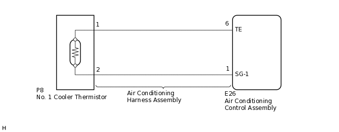
The No. 1 cooler thermistor is installed on the evaporator in the air conditioner unit to detect the temperature of the cooled air that has passed through the evaporator, which is used to control the air conditioning system. It sends signals to the air conditioning control assembly. The resistance of the No. 1 cooler thermistor changes in accordance with the temperature of the cooled air that has passed through the evaporator. As the temperature decreases, the resistance increases. As the temperature increases, the resistance decreases.
The air conditioning control assembly applies voltage (5 V) to the No. 1 cooler thermistor and reads voltage changes as the resistance of the No. 1 cooler thermistor changes. This sensor is used for frost prevention.
WIRING DIAGRAM
PROCEDURE
CHECK AIR CONDITIONING HARNESS ASSEMBLY (NO. 1 COOLER THERMISTOR - AIR CONDITIONING CONTROL ASSEMBLY)
Disconnect the E26 air conditioning control assembly connector.
Disconnect the P8 No. 1 cooler thermistor connector.
Measure the resistance according to the value(s) in the table below.
Standard Resistance
Tester Connection
Condition
Specified Condition
P8-1 - E26-6 (TE)
Always
Below 1 Ω
P8-2 - E26-1 (SG-1)
Always
Below 1 Ω
P8-1 - Body ground
Always
10 kΩ or higher
P8-2 - Body ground
Always
10 kΩ or higher
Result
Proceed to
OK
NG
INSPECT NO. 1 COOLER THERMISTOR
Remove the No. 1 cooler thermistor.
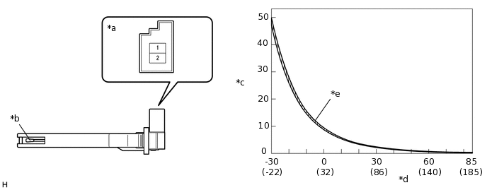
*a
Component without harness connected
(No. 1 Cooler Thermistor)
*b
Sensing Portion
*c
Resistance (kΩ)
*d
Temperature (°C (°F))
*e
Allowable Range
-
-
Measure the resistance according to the value(s) in the table below.
Standard Resistance
Tester Connection
Condition
Specified Condition
1 - 2
-30°C (-22°F)
47.59 to 49.99 kΩ
-25°C (-13°F)
35.12 to 36.76 kΩ
-20°C (-4°F)
26.19 to 27.33 kΩ
-15°C (5°F)
19.71 to 20.50 kΩ
-10°C (14°F)
14.97 to 15.53 kΩ
-5°C (23°F)
11.47 to 11.86 kΩ
0°C (32°F)
8.87 to 9.14 kΩ
5°C (41°F)
6.88 to 7.12 kΩ
10°C (50°F)
5.39 to 5.59 kΩ
15°C (59°F)
4.25 to 4.41 kΩ
20°C (68°F)
3.37 to 3.51 kΩ
25°C (77°F)
2.70 to 2.82 kΩ
30°C (86°F)
2.17 to 2.27 kΩ
35°C (95°F)
1.76 to 1.84 kΩ
40°C (104°F)
1.43 to 1.51 kΩ
45°C (113°F)
1.17 to 1.24 kΩ
50°C (122°F)
0.97 to 1.02 kΩ
55°C (131°F)
0.80 to 0.85 kΩ
60°C (140°F)
0.66 to 0.71 kΩ
65°C (149°F)
0.56 to 0.59 kΩ
70°C (158°F)
0.47 to 0.50 kΩ
75°C (167°F)
0.40 to 0.42 kΩ
80°C (176°F)
0.34 to 0.36 kΩ
85°C (185°F)
0.29 to 0.31 kΩ
Note:Hold the sensor only by its connector. Touching the sensing portion may change the resistance value.
When measuring, the sensor temperature must be the same as the ambient temperature.
Tip:As the temperature increases, the resistance decreases (see the graph).
Result
Proceed to
OK
NG