BRAKE BOOSTER(for RHD) INSTALLATION
PROCEDURE
INSTALL BRAKE BOOSTER GASKET
Install a new brake booster gasket to the brake booster assembly.
INSTALL BRAKE BOOSTER ASSEMBLY
Temporarily install the brake booster assembly to the vehicle body.
Note:Do not apply excessive force to the brake lines or refrigerant lines.
Temporarily install the lock nut and brake master cylinder push rod clevis to the brake booster assembly.
Note:Fully tighten the lock nut when adjusting the brake pedal height.
-
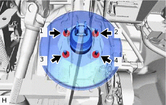
Install the 4 nuts to secure the brake booster assembly.
16 N*m
163 kgf*cm
12 ft.*lbf
Note:Tighten the 4 nuts in the order shown in the illustration.
INSTALL PUSH ROD PIN
INSTALL ENGINE ROOM MAIN WIRE
-
Engage the 3 clamps to install the engine room main wire to the vehicle body.
Install the 2 ground wires with the 2 bolts.
8.4 N*m
86 kgf*cm
74 in.*lbf
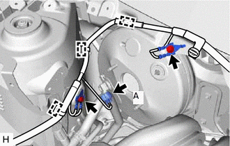
for 1KR-FE with Stop and Start System, 1PP:
Connect the connector (A) to the vacuum sensor assembly.
-
INSTALL AIR CONDITIONER HOSE AND ACCESSORY (for 1PP with Air Conditioning System)
Install the air conditioner hose and accessory to the vehicle body with the bolt.
9.8 N*m
100 kgf*cm
87 in.*lbf
Note:Do not deform the refrigerant lines.
INSTALL RADIATOR RESERVE TANK ASSEMBLY (for 1PP with Air Conditioning System)
-
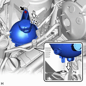
*a
Grommet
Install the radiator reserve tank assembly and engage the guide and grommet as shown in the illustration.
Install the bolt to secure the radiator reserve tank assembly.
7.5 N*m
76 kgf*cm
66 in.*lbf
-
INSTALL BRAKE LINE
Engage the 2 clamps to install the 2 brake lines to the No. 2 brake tube clamp and No. 3 brake tube clamp.
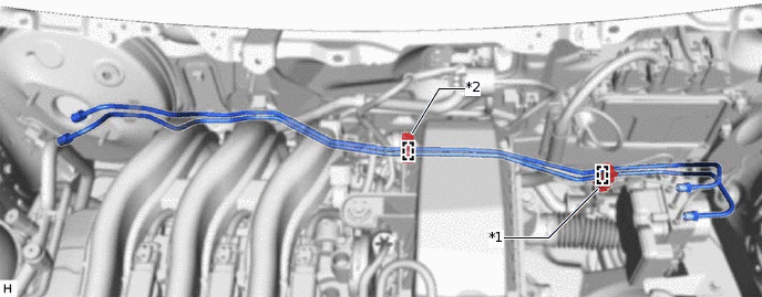
*1
No. 2 Brake Tube Clamp
*2
No. 3 Brake Tube Clamp
-
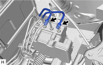
Temporarily tighten the 2 brake lines to the correct positions on the brake actuator assembly as shown in the illustration.
Using a union nut wrench, fully tighten 2 brake lines.
w/o VSC
15.2 N*m
155 kgf*cm
11 ft.*lbf
w/ VSC
19.5 N*m
199 kgf*cm
14 ft.*lbf
Note:Do not kink or damage the brake lines.
Do not allow the brake lines to twist or interfere with other parts or the vehicle body during tightening.
Do not allow any foreign matter such as dirt or dust to enter the brake lines from the connecting parts.
Use the formula to calculate special torque values for situations where the union nut wrench is combined with a torque wrench.
INSTALL CLUTCH RELEASE CABLE CLAMP (for 1PP)
INSTALL RELAY BLOCK BRACKET
INSTALL BATTERY CLAMP SUB-ASSEMBLY
for 1KR-FE:Click hereClick here
for 1PP:Click here
INSTALL BATTERY
for 1KR-FE:Click hereClick here
for 1PP:Click here
INSTALL VACUUM HOSE ASSEMBLY
Align the vacuum hose assembly connector with the intake manifold pipe, and push the vacuum hose assembly connector until it makes a "click" sound.
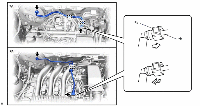
*A
for 1KR-FE
*B
for 1PP
*a
Vacuum Hose Assembly Connector
*b
Intake Manifold Pipe

Push

Pull
After connecting the vacuum hose assembly, check that the intake manifold pipe and vacuum hose assembly connector are securely connected by pulling on them.
for 1KR-FE:
Engage the 2 clamps to install the vacuum hose assembly.
for 1PP:
Engage the clamp to install the vacuum hose assembly.
Connect the vacuum hose assembly to the brake booster assembly.
INSTALL BRAKE MASTER CYLINDER SUB-ASSEMBLY
CONNECT CABLE TO NEGATIVE BATTERY TERMINAL
Note:When disconnecting the cable, some systems need to be initialized after the cable is reconnected.
INSPECT AND ADJUST BRAKE PEDAL