MANUAL TRANSAXLE UNIT REASSEMBLY

PROCEDURE
-
INSTALL NO. 3 GEAR SHIFT FORK SHAFT
-
Install the No. 3 gear shift fork shaft to the No. 3 gear shift fork with a new bolt.
- Torque:
- 20 N*m { 199 kgf*cm, 14 ft.*lbf }
-
-
INSTALL NO. 1 GEAR SHIFT FORK SHAFT
-
Install the No. 1 gear shift fork shaft to the No. 1 gear shift fork with a new bolt.
- Torque:
- 20 N*m { 199 kgf*cm, 14 ft.*lbf }
-
Using a brass bar and a hammer, install a new shaft snap ring.
-
Install the No. 1 gear shift fork shaft together with the No. 1 gear shift fork to the No. 3 gear shift fork shaft and No. 3 gear shift fork.
-
Using a brass bar and a hammer, install a new shaft snap ring.
-
-
INSTALL NO. 2 GEAR SHIFT FORK SHAFT
-
Install the No. 2 gear shift fork shaft to the No. 2 gear shift fork with a new bolt.
- Torque:
- 20 N*m { 199 kgf*cm, 14 ft.*lbf }
-
Using a brass bar and a hammer, install a new shaft snap ring.
-
-
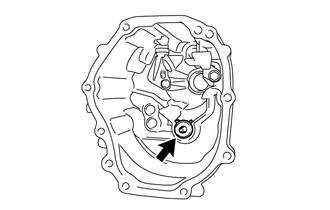
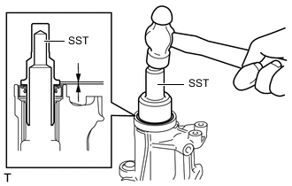
INSTALL TRANSMISSION FRONT BEARING RETAINER OIL SEAL
-
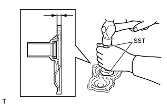
Using SST and a hammer, install a new transmission front bearing retainer oil seal.
- SST
- 09950-60010 ( 09951-00420 )
- 09950-70010 ( 09951-07100 )
Installation depth 11.1 to 11.9 mm (0.437 to 0.469 in.) (from the end surface of the front bearing retainer) Note
-
Do not damage the lip of the transmission front bearing retainer oil seal.
-
Do not damage the front bearing retainer.
-
Apply MP grease to the lip of the transmission front bearing retainer oil seal.
-
-
INSTALL REVERSE IDLER GEAR SHAFT
-
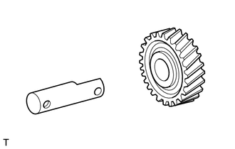
Apply manual transmission gear oil to the reverse idle gear shaft, and then install it to the reverse idler gear.
-
-
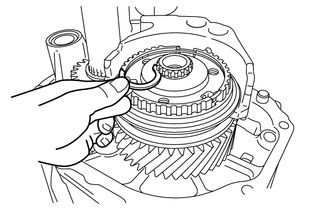
INSTALL INPUT SHAFT
-
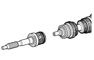
Apply manual transmission gear oil to the needle roller bearing of the input shaft, and then install the input shaft to the output shaft.
-
-
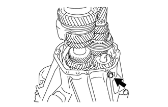
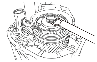
INSTALL COUNTER SHAFT
-
Install the input shaft, output shaft, counter shaft, reverse idler gear, reverse idler gear shaft, No. 1 gear shift fork shaft, No. 2 gear shift fork shaft and No. 3 gear shift fork shaft all together to the clutch housing.

-
Using a new gasket and a new bolt, temporarily install the reverse idler gear shaft (clutch housing side).
-
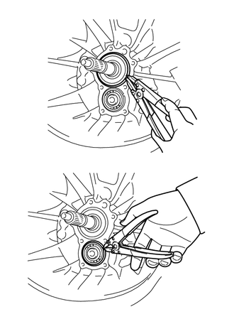
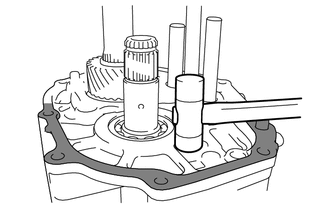
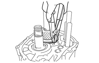
Using a snap ring expander, install 2 new shaft snap rings.
Tech Tips
Install the shaft snap rings to the input shaft and counter shaft.
-
-
INSTALL FRONT BEARING RETAINER
-
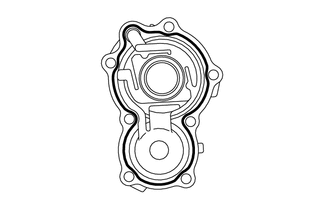
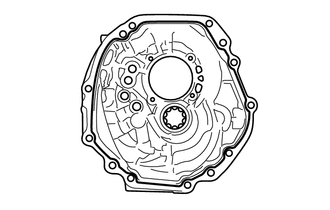
Apply seal packing 1281 continuously to the front bearing retainer as shown in the illustration.
Text in Illustration 
Seal Packing 1281 Note
Install it within 10 minutes of the seal packing application.
-
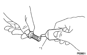
Text in Illustration *1 Adhesive 1344 Apply adhesive 1344 to the 2nd and 3rd pitches from the tip of new bolt.
-
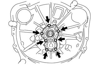
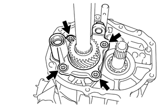
Install the front bearing retainer with the 7 bolts.
- Torque:
- 17 N*m { 173 kgf*cm, 13 ft.*lbf }
Note
Install the front bearing retainer ensuring that the transmission front bearing retainer oil seal lip is not damaged.
-
-
INSTALL OIL RECEIVER PIPE
-
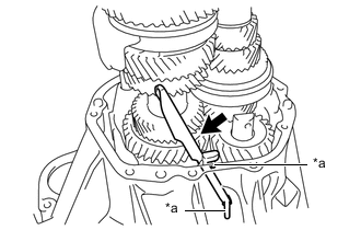
Text in Illustration *a Protrusion Install the oil receiver pipe.
Note
Confirm that the protrusions of the oil receiver pipe are properly fitted in the grooves.
-
-
INSTALL TRANSMISSION CASE
-
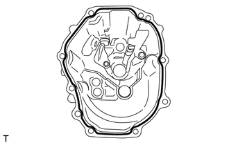
Apply seal packing 1281 continuously to the transmission case as shown in the illustration.
Text in Illustration Seal Packing 1281 Note
Install within 10 minutes of the seal packing application.
-
Check the location of the knock pin, and then using a plastic hammer, install the transmission case.
Text in Illustration 
Do not hit hard. -
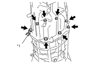
Text in Illustration *1 Adhesive 1324 Apply adhesive 1324 to the 2nd and 3rd pitches.
-
Text in Illustration *1 clamp Install the transmission case and clamp with the 9 bolts.
- Torque:
- 29 N*m { 296 kgf*cm, 21 ft.*lbf }
-
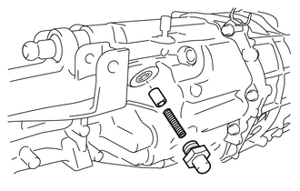
Install a new reverse idler gear shaft fixing bolt and new gasket (transmission case side).
- Torque:
- 28 N*m { 286 kgf*cm, 21 ft.*lbf }
-
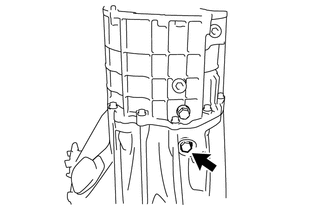
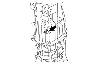
Securely tighten the reverse idler gear shaft fixing bolt (clutch housing side).
- Torque:
- 28 N*m { 286 kgf*cm, 21 ft.*lbf }
-
Using a snap ring expander, install a new shaft snap ring.
-
-
INSTALL REAR BEARING RETAINER
-
Install the shift arm pivot to the rear bearing retainer.
-
Text in Illustration *1 Adhesive 1324 Apply adhesive 1324 to the 2nd and 3rd pitches from the tip of new bolt.
-
Using a T45 "TORX" socket wrench, install the rear bearing retainer with the 4 bolts.
- Torque:
- 30 N*m { 306 kgf*cm, 22 ft.*lbf }
-
-
INSTALL 6TH GEAR THRUST WASHER
-
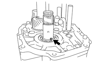
Install the straight pin to the counter shaft.
-
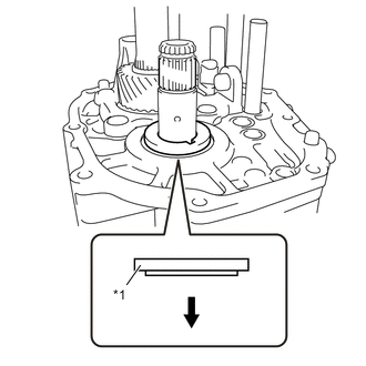
Text in Illustration *1 6th Gear Thrust Washer 
Front Side Apply manual transmission gear oil to the 6th gear thrust washer.
-
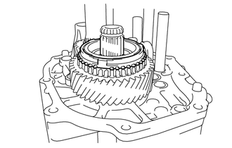
As shown in the illustration, install the 6th gear thrust washer to the counter shaft.
-
-
INSTALL NEEDLE ROLLER BEARING
-
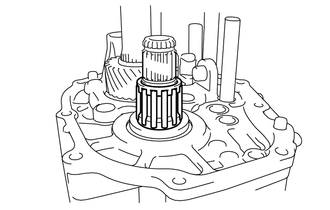
Apply manual transmission gear oil to the needle roller bearing, and then install the needle roller bearing to the counter shaft.
-
-
INSTALL COUNTER SHAFT 6TH GEAR
-
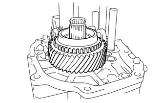
Apply manual transmission gear oil to the counter shaft 6th gear, and then install the counter shaft 6th gear to the counter shaft.
-
-
INSTALL NO. 2 SYNCHRONIZER RING
-
Apply manual transmission gear oil to the No. 2 synchronizer ring, and then install the No. 2 synchronizer ring to the counter shaft.
-
-
INSTALL NO. 4 TRANSMISSION HUB SLEEVE
-
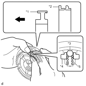
Text in Illustration *1 No. 4 Transmission Clutch Hub *2 No. 4 Transmission Hub Sleeve *3 Ball *4 No. 1 Synchromesh Shifting Key *5 No. 1 Synchromesh Shifting Key Spring Front Side Apply manual transmission gear oil to the moving parts of the No. 4 transmission clutch hub.
-
As shown in the illustration, install the No. 4 transmission hub sleeve to the No. 4 transmission clutch hub, and install the 3 No. 1 synchromesh shifting keys and 3 No. 1 synchromesh shifting key springs all together, and then install the 3 balls.
Tech Tips
-
Install the ball while holding down the No. 1 synchromesh shifting key spring.
-
After the installation, settle the No. 1 synchromesh shifting key spring.
-
-
Install a new hole snap ring.
-
-
INSTALL NO. 4 TRANSMISSION CLUTCH HUB
-
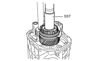
Using SST and a press, install the No. 4 transmission clutch hub, No. 4 transmission hub sleeve, and No. 4 gear shift fork all together.
- SST
- 09632-36010
Tech Tips
-
Align the No. 4 transmission clutch hub and the No. 2 synchronizer ring so that they can fit together.
-
Engage the No. 4 gear shift fork with the groove of the No. 4 transmission hub sleeve.
-
-
INSTALL SHAFT SNAP RING
-
Select a shaft snap ring that is suitable to retain the specific thrust clearance between the No. 4 transmission clutch hub and shaft snap ring.
Standard clearance 0 to 0.1 mm (0 to 0.00394 in.) Tech Tips
Select the thickest shaft snap ring possible for installation.
Shaft Snap Ring Thickness Part No. Thickness mm (in.) Mark SU003-03552 2.80 (0.11023) A SU003-03553 2.85 (0.11220) B SU003-03554 2.90 (0.11417) C SU003-03555 2.95 (0.11614) D SU003-03556 3.00 (0.11811) E SU003-03557 3.05 (0.12007) F -
Using a brass bar and a hammer, install a new shaft snap ring to the counter shaft.
-
-
INSTALL NO. 2 GEAR SHIFT HEAD
-
Install the No. 2 gear shift head to the No. 2 gear shift fork shaft.
-
Using a 5 mm pin punch and a hammer, install a new slotted spring pin to the No. 2 gear shift fork shaft.
Note
Do not tap the pin too deep.
Standard depth 0 mm (0 in.) (from the end surface of the No. 2 gear shift head)
-
-
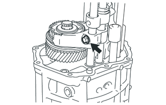
INSTALL 5TH SHIFT HEAD
-
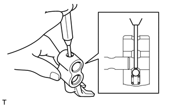
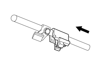
Install the compression spring to the 5th shift head, and then, while holding down the ball with the 5 mm pin punch, install the 5th shift head to the No. 3 gear shift fork shaft.
-
Install the washer.
-
Using a brass bar and a hammer, install a new shaft snap ring to the No. 3 gear shift fork shaft.
-
-
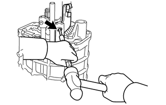
INSTALL NO. 3 GEAR SHIFT FORK SHAFT
-
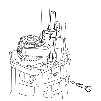
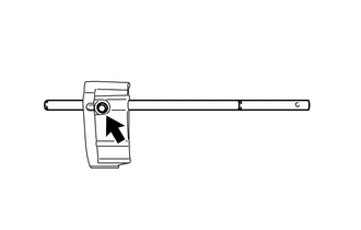
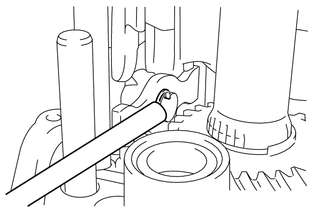
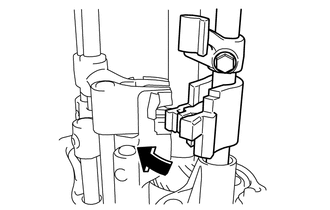
As shown in the illustration, insert the No. 3 gear shift fork shaft. Using a T40 "TORX" socket wrench, install the ball and compression spring, and then tighten with a new head straight screw plug.
- Torque:
- 19 N*m { 194 kgf*cm, 14 ft.*lbf }
-
-
INSTALL SHIFT ARM
-
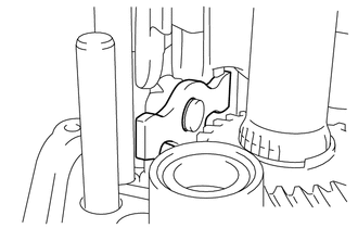
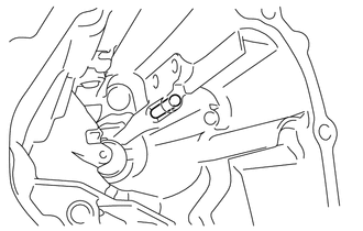
Install the shift arm to the shift arm pivot.
-
Using a brass bar and a hammer, install a new E- ring to the shift arm pivot.
-
-
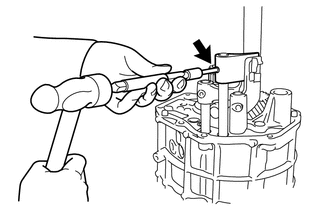
INSTALL NO. 2 GEAR SHIFT FORK SHAFT
-
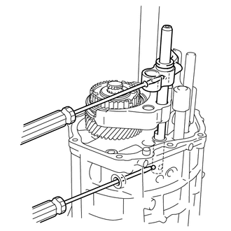
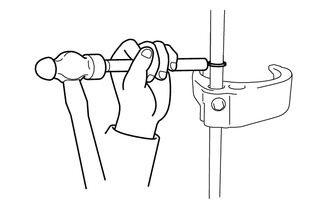
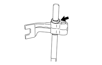
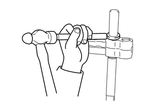
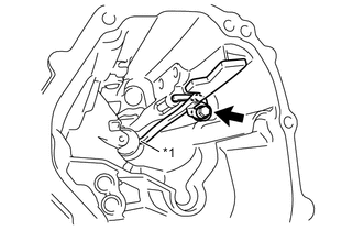
Using a screwdriver, install the 2 balls to the No. 3 gear shift fork shaft.
Tech Tips
Support the ball with the screwdriver so that the ball does not fall off.
-
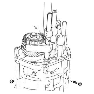
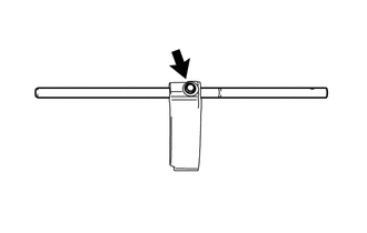
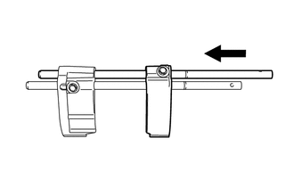
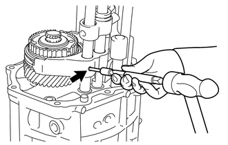
Text in Illustration *a Identification Hole While the identification hole is facing towards the outside, insert the No. 2 gear shift fork shaft. And then, using a T40 "TORX" socket wrench, install the ball and compression spring, and then tighten 2 new head straight screw plugs.
- Torque:
- 19 N*m { 194 kgf*cm, 14 ft.*lbf }
-
for Pin:
-
Using a 5 mm pin punch and a hammer, install a new slotted spring pin to the No. 2 gear shift fork shaft.
Note
Do not tap the pin too deep.
Standard depth 0 mm (0 in.) (from the end surface of the No. 4 gear shift fork)
-
-
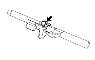
for Bolt:
-
Install a new bolt to the No. 2 gear shift fork shaft.
- Torque:
- 20 N*m { 199 kgf*cm, 14 ft.*lbf }
-
-
-
INSTALL NO. 3 GEAR SHIFT HEAD
-
Install the No. 3 gear shift head to the No. 3 gear shift fork shaft.
Tech Tips
While rotating, install the No. 3 gear shift head so that the shift arm is engaged with the groove of the No. 3 gear shift head.
-
Using a 5 mm pin punch and a hammer, install a new slotted spring pin to the No. 3 gear shift fork shaft.
Note
Do not tap the pin too deep.
Standard depth 0 mm (0 in.) (from the end surface of the No. 3 gear shift head)
-
-
INSTALL NO. 1 GEAR SHIFT HEAD
-
Install the No. 1 gear shift head to the No. 1 gear shift fork shaft.
-
Using a 5 mm pin punch and a hammer, install a new slotted spring pin to the No. 1 gear shift fork shaft.
Note
Do not tap the pin too deep.
Standard depth 0 mm (0 in.) (from the end surface of the No. 1 gear shift head)
-
-
INSTALL FRONT SHIFT INNER LEVER
-
Text in Illustration *1 Adhesive 1324 Apply adhesive 1324 to the 2nd and 3rd pitches from the tip of new bolt.
-
Install the front shift inner lever to the shift shaft with a new bolt.
- Torque:
- 33 N*m { 340 kgf*cm, 25 ft.*lbf }
-
-
INSTALL NO. 1 SHIFT INTER LOCK BLOCK
-
Install the No. 1 shift inter lock block to the shift shaft.
-
-
INSTALL SHIFT SHAFT
-
Install the shift shaft and No. 1 shift inter lock block by sliding them.
-
-
INSTALL NO. 1 EXTENSION HOUSING OIL RECEIVER PIPE
-
Install the straight pin.
-
Text in Illustration *1 No. 1 Extension Housing Oil Receiver Pipe End Install the No. 1 extension housing oil receiver pipe and stopper plate with a new bolt.
- Torque:
- 8.5 N*m { 87 kgf*cm, 75 in.*lbf }
Note
Confirm that the end of No. 1 extension housing oil receiver pipe is properly fitted in the groove.
-
-
INSTALL NO. 2 EXTENSION HOUSING OIL RECEIVER PIPE
-
Install the No. 2 extension housing oil receiver pipe.
-
-
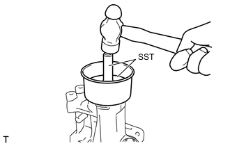
INSTALL TRANSMISSION EXTENSION HOUSING OIL SEAL
-
Apply MP grease to the lip of the new transmission extension housing oil seal.
-
Using SST and a hammer, install a new transmission extension housing oil seal.
- SST
- 09325-20010
Installation depth 0.1 to 1.1 mm (0.00394 to 0.0433 in.) (from the end surface of the transmission extension housing sub-assembly) Note
Do not damage the lip of the transmission extension housing oil seal.
-
-
INSTALL EXTENSION HOUSING DUST DEFLECTOR
-
Using SST and a hammer, install a new extension housing dust deflector.
- SST
- 09950-60020 ( 09951-00750 )
- 09950-70010 ( 09951-07100 )
Tech Tips
Make sure to tap it until it touches the transmission extension housing sub-assembly.
-
-
INSTALL EXTENSION HOUSING REAR OIL SEAL
-
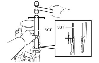
Using SST and a hammer, install a new extension housing rear oil seal.
- SST
- 09612-70100 ( 09612-07210 )
Installation depth 1.0 to 2.0 mm (0.0394 to 0.0787 in.) (from the end surface of the transmission extension housing sub-assembly) Note
Do not damage the lip of the extension housing rear oil seal.
-
Apply MP grease to the lip of the extension housing rear oil seal.
-
-
INSTALL TRANSMISSION EXTENSION HOUSING SUB-ASSEMBLY
-
Apply seal packing 1281 continuously to the transmission extension housing sub-assembly as shown in the illustration.
Text in Illustration Seal Packing 1281 Note
Install it within 10 minutes of the seal packing application.
-
Text in Illustration *1 clamp Install the transmission extension housing sub-assembly and clamp with 8 new bolts.
- Torque:
- 29 N*m { 296 kgf*cm, 21 ft.*lbf }
Note
-
Be sure to install the transmission extension housing sub-assembly while the transmission is in neutral.
-
Make sure to align the knock pin with the hole securely.
-
Install a new bolt.
- Torque:
- 31 N*m { 316 kgf*cm, 23 ft.*lbf }
-
-
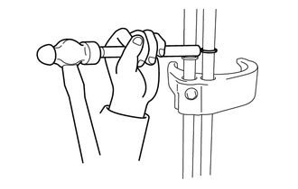
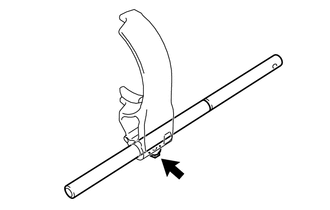
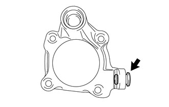
INSTALL HOLDER
-
Using a 27 mm deep socket wrench, install a new holder, compression spring and lock ball pin.
- Torque:
- 39 N*m { 400 kgf*cm, 29 ft.*lbf }
-
-
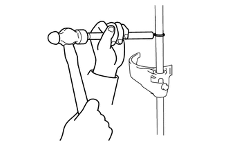
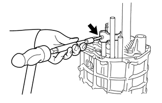
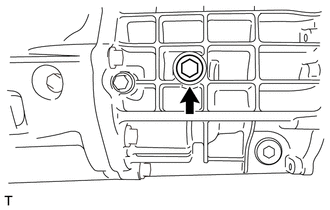
INSTALL LOCK BALL PIN
-
Using a 10 mm hexagon socket wrench, install a new head straight screw plug, compression spring and lock ball pin.
- Torque:
- 25 N*m { 250 kgf*cm, 18 ft.*lbf }
-
-
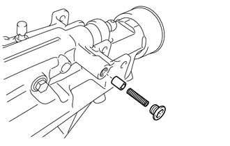
INSTALL WIRE HARNESS CLAMP BRACKET
-
Install the wire harness clamp bracket with a new bolt.
- Torque:
- 7.0 N*m { 71 kgf*cm, 62 in.*lbf }
-
-
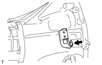
INSTALL NEUTRAL POSITION SWITCH ASSEMBLY
-
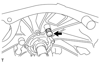
Using a 19 mm union nut wrench, install the neutral position switch assembly and a new gasket.
- Torque:
- 32 N*m { 329 kgf*cm, 24 ft.*lbf }
Note
Use the formula to calculate special torque values for situations where the union nut wrench is combined with a torque wrench Click here.
-
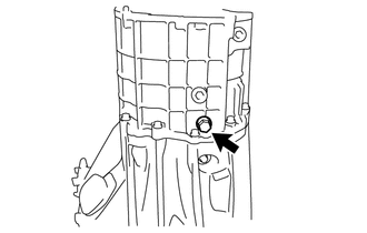
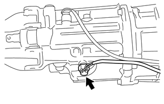
Engage the clamp and connect the neutral position switch assembly wire.
-
-
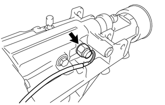
INSTALL BACK-UP LIGHT SWITCH ASSEMBLY
-
Using a 19 mm union nut wrench, install the back-up light switch assembly and a new gasket.
- Torque:
- 32 N*m { 329 kgf*cm, 24 ft.*lbf }
Note
Use the formula to calculate special torque values for situations where the union nut wrench is combined with a torque wrench Click here.
-
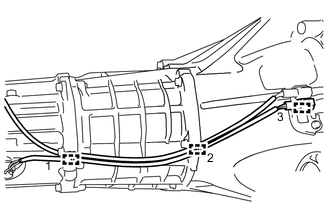
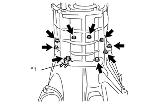
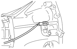
In the order indicated in the illustration, engage the 3 clamps in place, and connect the back-up light switch assembly wire and neutral position switch assembly wire.
Tech Tips
Install the wire harness so that there is slack on the connector side.
-
-
INSTALL RELEASE FORK SUPPORT
-
Using a 19 mm deep socket wrench, install the release fork support to the clutch housing.
- Torque:
- 16 N*m { 163 kgf*cm, 12 ft.*lbf }
-
-
INSTALL MANUAL TRANSMISSION DRAIN PLUG
-
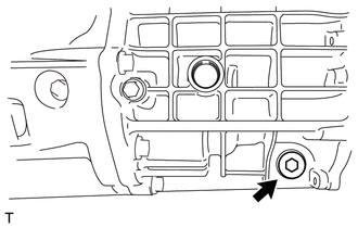
Install the manual transmission drain plug with a new gasket to the transmission case.
- Torque:
- 37 N*m { 377 kgf*cm, 27 ft.*lbf }
-
-
INSTALL MANUAL TRANSMISSION FILLER PLUG
-
Install the manual transmission filler plug with a new gasket to the transmission case.
- Torque:
- 37 N*m { 377 kgf*cm, 27 ft.*lbf }
-