METER / GAUGE SYSTEM
-
OPERATING CONDITION
-
Hybrid System Indicator
-
The Hybrid System Indicator will begin to operate when both of the following conditions are met:
-
The hybrid system is operating (the READY indicator light is illuminated).
-
Drive (D) or Brake (B) has been selected.
-
-
Eco Driving Indicator Light can begin to operate when all of the following conditions are met:
-
The hybrid system is operating (the READY indicator light is illuminated).
-
Drive (D) has been selected.
-
The Hybrid System Indicator is in the Charge area or Eco area.
-
EV mode is not selected.
-
The hybrid system is normal.
-
The hybrid system temperature is normal.
-
The vehicle is at a speed of about 130 km/h (81 mph) or below.
-
-
-
-
FUNCTION
-
Combination Meter Sub-assembly
-
Buzzer Function
-
The table below shows the warning and reminder functions of the buzzer in the combination meter sub-assembly.
1 READY 2 Shift Position R Indication 3 Seat Belt Warning (Level 2) 4 Rear Seat Belt Warning (Level 1) 5 Front Seat Belt Warning (Level 1) 6 Brake System Warning 7 Hybrid Battery Diagnosis Request (Second Time) 8 EPS Warning 9 Entry and Start System Warning (Continuous) 10 Entry and Start System Warning (Intermittent) 11 Brake Operation Active Check Indication 12 Hill-start Assist Control Indication 13 Entry and Start System Warning (Once) 14 Hybrid System Warning 15 Accelerator Depression with Neutral (N) Selected 16 Dynamic Radar Cruise Control Cancellation due to Low Vehicle Speed* 17 Dynamic Radar Cruise Control Warning* 18 Immobiliser Certification Reminder 19 Low Fuel Indicator 20 P Position Request 21 HV Battery Low Warning 22 HV Battery Charge Request 23 Parking Brake Engaged Warning 24 Door Open while Driving Warning 25 Shift Operation Reject Warning 26 EV Drive Mode Reject Warning 27 Headlight Reminder 28 Turn Signal/Hazard Warning Operation
*: Models with dynamic radar cruise control system
-
-
Trip Information Display
-
The trip information is displayed in the following order each time the DISP switch of the steering pad switch assembly is pressed.
-
3 different average fuel consumption values can be displayed, one each for the odometer, TRIP A and TRIP B. When the DISP switch is pressed, the average fuel consumption for the currently displayed item (odometer, TRIP A or TRIP B) will be displayed.
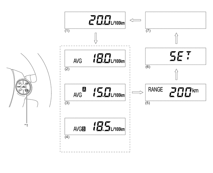
Text in Illustration *1 DISP Switch - - 
DISP switch pressed briefly. - - -
The trip information items displayed are as follows:
No. Information Outline (1) Current Fuel Consumption
-
Displays a value that has been calculated by the combination meter sub-assembly. When the power switch is turned on (IG), the combination meter sub-assembly calculates this value based on the distance driven and the volume of fuel consumed (fuel injection signal from the No. 1 cylinder).
-
This display is updated every 0.5 seconds.
(2) Average Fuel Consumption
-
Displays a value that has been calculated by the combination meter sub-assembly based on the distance driven and the volume of fuel consumed (fuel injection signal from the No. 1 cylinder).
-
This display is updated every 10 seconds.
(3) Average Fuel Consumption (TRIP A)
-
Displays a value that has been calculated by the combination meter sub-assembly based on the distance driven and the volume of fuel consumed (fuel injection signal from the No. 1 cylinder).
-
Separately calculates the average fuel consumption for TRIP A and TRIP B and displays the corresponding value.
-
Displays a blank screen if the fuel consumption volume data is not received due to a communication malfunction.
-
This display is updated every 10 seconds.
(4) Average Fuel Consumption (TRIP B) (5) Cruising Range
-
Displays a value that has been calculated by the combination meter sub-assembly. When the power switch is turned on (IG), the combination meter sub-assembly calculates the range based on continuously monitoring and storing information on fuel consumption data, and the residual fuel volume.
-
This display is updated every 10 seconds.
(6) Settings Changes which of the following items are displayed: Hybrid System Indicator, Eco Driving Indicator Light and the EV Driving Indicator Light. (7) Blank - -
-
In the SET screen, pressing and holding the DISP switch enters setting mode.
-
In setting mode, it is possible to select whether to display all or some of the following items: Hybrid System Indicator, Eco Driving Indicator Light and EV Driving Indicator Light.
Display Pattern Display Item 1
-
Hybrid System Indicator
-
Eco Driving Indicator Light
-
EV Driving Indicator Light
2
-
Hybrid System Indicator
-
EV Driving Indicator Light
3 Hybrid System Indicator 4 Blank 5 Eco Driving Indicator Light -
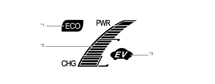
Text in Illustration *1 Eco Driving Indicator Light *2 Hybrid System Indicator *3 EV Drive Indicator Light - - -
-
-
Rear Seat Belt Warning
-
The combination meter assembly displays the rear seat belt warning based on the rear seat belt buckle switches and courtesy switches for the rear doors. If a warning is necessary, the buzzer in the combination meter assembly will also sound.
-
The flow of operations that results in a rear seat belt warning is as follows:
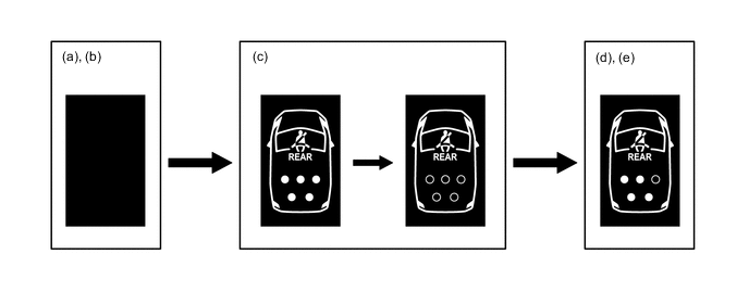
Step Condition Transition Multi-information Display Buzzer (a) Power switch is off. Warning is not displayed. No Sound (b) A rear door is opened then closed. (c)
-
Power switch is turned on (IG).
-
A seat belt is fastened.
-
In this case, all seats will be displayed as being unfastened regardless of the number of occupants. If seat belts are then fastened, the display for the relevant seat will go off.
-
The warning will be displayed for approximately 34 seconds and then go off.
(d) Any of the rear seat belts are unfastened.
-
Seats with an unfastened seat belt will be displayed regardless of the number of occupants.
If the vehicle speed exceeds 20 km/h (12 mph):
-
Sounds for 30 seconds*1
-
Sounds for an additional 90 seconds*2
(e)
-
When one of the following conditions is met, the buzzer will stop sounding.
-
The seat belt is refastened.
-
Vehicle speed is lower than approximately 2 km/h (1.2 mph) and either the parking brake is applied or the P position switch is pressed.
-
Seats with an unfastened seat belt will be displayed regardless of the number of occupants.
-
The warning message will be displayed for approximately 34 seconds and then go off.
Stops sounding *1: Sound cycle is 1.2 seconds.
*2: Sound cycle is 0.4 seconds.
-
-
-
Headup Display Customize
-
The items displayed on the headup display can be customized.
-
Pressing and holding the SET switch changes the headup display to setting mode, enabling each display to be enabled or disabled.
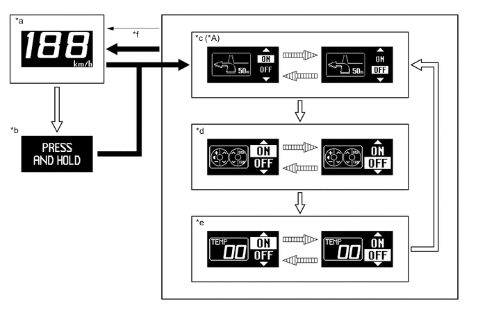
Text in Illustration *A Models with HDD Navigation System - - *a Vehicle Speed Display *b Advisory Display of Switching to On/off Setting Mode *c Turn-by-turn Navigation ON/OFF Setting *d Touch Tracer ON/OFF Setting *e Feedback Screen ON/OFF Setting *f Returns to the normal headup display when vehicle speed reaches 8 km/h (5 mph) or when 10 seconds have elapsed without any operation. 
SET switch is pressed and held. SET switch is pressed briefly. 
Position adjustment switch is operated. - -
-
-
-
CONSTRUCTION
-
Headup Display
-
The headup display projects the image from the dot Vacuum Fluorescent Display (VFD), built into the headup display unit (combination meter mirror ECU), in a position approximately 2 m (6.6 ft) forward of the driver using a concave mirror and the windshield in order to support the driver with various information.
-
By changing the angle of the concave mirror, the position of the image displayed can be adjusted.
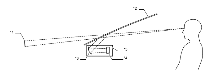
Text in Illustration *1 Headup Display Image *2 Windshield Glass *3 Concave Mirror *4 Dot VFD *5 Headup Display Unit (Combination Meter Mirror ECU) - -
-
-
Windshield Glass for Headup Display
-
Windshield glass without a combiner treatment is used for the headup display.
-
This glass has a wedge-shaped inner film. This film, with its varying thickness, is located between the outer and inner layers of glass.
-
The light that strikes the glass is reflected by the inner surface of the inner glass, and also by the inner side of the outer surface of outer layer of glass. With a conventional windshield, the light reflected from these 2 surfaces diverges due to the thickness of the glass, resulting in a double image.
-
The film's wedge shape is used to eliminate the reflection angle difference between the outer glass and inner glass. This recombines the reflected light and eliminates the double image.
-
Thus, the reflected light from the headup display unit is seen by the driver as a single display image.
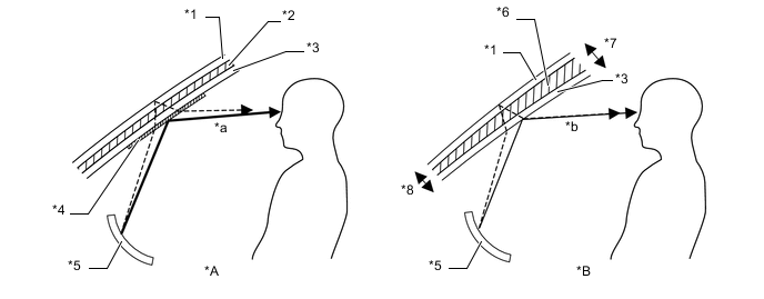
Text in Illustration *A Windshield Glass with Normal Film *B Windshield Glass with Wedge-shaped Film *1 Outer Glass *2 Uniform Thickness Film *3 Inner Glass *4 Combiner *5 Concave Mirror *6 Wedge-shaped Film *7 Thick *8 Thin *a The combiner makes the light reflected by the inner glass brighter, however, a double image is caused by a divergence of the reflected light. *b Reflected light is recombined and a double image is prevented.
-
-
Steering Pad Switch Assembly
-
The steering pad switch are provided with pressure-sensitive touch sensors. The touch tracer display in headup display is displayed when any of the switches is touched by the driver.
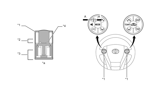
Text in Illustration *1 Steering Pad Switch *2 Touch Switch Area *3 Function Switch Area *4 Touch Sensor *5 Touch Tracer Display - - *a A-A Cross Section - -
-
-