POWER MANAGEMENT CONTROL ECU(for RHD) INSTALLATION
CAUTION / NOTICE / HINT
A bolt without a torque specification is shown in the standard bolt chart (Click here).
PROCEDURE
INSTALL POWER MANAGEMENT CONTROL ECU (for Type A)
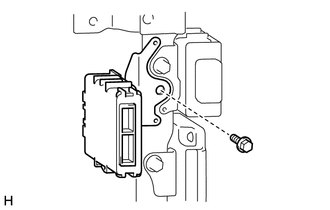
Install the power management control ECU with the bolt.
13 N*m
127 kgf*cm
9 ft.*lbf
Connect each connector.
Install the fuse box opening cover (Click here).
Install the No. 2 switch hole base (Click here).
Install the instrument panel finish panel end RH (Click here).
INSTALL POWER MANAGEMENT CONTROL ECU (for Type B, for Type C)
Install the power management control ECU with the 3 bolts.
for Bolt A
13 N*m
127 kgf*cm
9 ft.*lbf
Connect each connector.
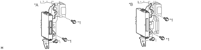
Table 1. Text in Illustration *A
for Type B
*B
for Type C
*1
Bolt A
-
-
Install the lower instrument panel sub-assembly (Click here).
Install the instrument panel safety pad sub-assembly (Click here).
CONNECT CABLE TO NEGATIVE BATTERY TERMINAL
Note:When disconnecting the cable, some systems need to be initialized after the cable is reconnected (Click here).