ENTRY AND START SYSTEM(for Entry Function) Back Door Entry Unlock Function does not Operate
| DTC Code | DTC Name |
|---|---|
| Back Door Entry Unlock Function does not Operate |
DESCRIPTION
If the entry unlock function does not operate for the back door only, but the entry lock function operates, the request code is being transmitted properly from the back door. In this case, there may be a problem related to the unlock switch (connection between the back door electrical key switch and certification ECU).
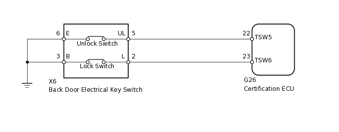
WIRING DIAGRAM
CAUTION / NOTICE / HINT
The entry and start system (for Entry Function) uses a multiplex communication system (LIN communication system) and the CAN communication system. Inspect the communication function by following How to Proceed with Troubleshooting (Click here). Troubleshoot the entry and start system (for Entry Function) after confirming that the communication systems are functioning properly.
When using the intelligent tester with the engine switch off to troubleshoot:
Connect the intelligent tester to the DLC3 and turn a courtesy light switch on and off at 1.5-second intervals until communication between the intelligent tester and vehicle begins.
Check that there are no electrical key transmitters in the vehicle.
When checking the entry lock operation multiple times, the lock operation may be limited to 2 consecutive operations depending on the settings. In order to perform the entry lock operation 3 or more times, an unlock operation must be performed once (any type of unlock operation is sufficient). However, only consecutive entry lock operations are limited. Using the wireless lock or other types of lock operations, it is possible to perform consecutive lock operations without this limitation.
Before replacing the certification ECU, refer to the entry and start system (for Entry Function) (Click here).
After repair, confirm DTC not reoccur with performing the "DTC Output Confirmation Operation".
PROCEDURE
CHECK POWER DOOR LOCK OPERATION
When the door control switch on the multiplex network master switch assembly is operated, check that the doors unlock and lock according to the switch operation
OK
Door locks operate normally.
Result
Result
OK
NG
READ VALUE USING INTELLIGENT TESTER (DOOR LOCK POSITION SWITCH)
Connect the intelligent tester to the DLC3.
Turn the engine switch on (IG).
Turn the intelligent tester on.
Enter the following menus: Body / Main Body / Data List.
Read the Data List according to the display on the intelligent tester.
Body Electrical > Main Body > Data List
Tester Display
Measurement Item
Range
Normal Condition
Diagnostic Note
Back Door Lock Pos SW
Back door lock
OFF or ON
ON: Back door unlocked
OFF: Back door locked
-
OK
On the intelligent tester screen, the display changes between ON and OFF as shown in the chart above.
Result
Result
OK
NG
NG GO TO POWER DOOR LOCK CONTROL SYSTEM (Proceed to Only Back Door Lock/Unlock Functions do not Operate)
READ VALUE USING INTELLIGENT TESTER (UNLOCK SWITCH)
Using the intelligent tester, read the Data List
Body Electrical > Entry&Start > Data List
Tester Display
Measurement Item
Range
Normal Condition
Diagnostic Note
Tr/B-Door Unlock SW
Back door electrical key switch (unlock switch)
ON or OFF
ON: Back door electrical key switch (unlock switch) pushed
OFF: Back door electrical key switch (unlock switch) not pushed
Displays whether the back door electrical key switch (unlock switch) is on or off.
Use this Data List item to help determine if there is a switch malfunction when the back door unlock function does not operate.
OK
The intelligent tester display changes correctly in response to the operation of the back door electrical key switch.
Result
Result
OK
NG
OK REPLACE CERTIFICATION ECU
CHECK HARNESS AND CONNECTOR (BACK DOOR ELECTRICAL KEY SWITCH - CERTIFICATION ECU)
Disconnect the X6 back door electrical key switch connector.
Disconnect the G26 certification ECU connector.
Measure the resistance according to the value(s) in the table below.
Standard Resistance
Tester Connection
Condition
Specified Condition
X6-5 (UL) - G26-22 (TSW5)
Always
Below 1 Ω
X6-6 (E) - Body ground
Always
Below 1 Ω
X6-5 (UL) or G26-22 (TSW5) - Body ground
Always
10 kΩ or higher
Result
Result
OK
NG
NG REPAIR OR REPLACE HARNESS OR CONNECTOR
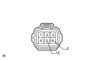
INSPECT BACK DOOR ELECTRICAL KEY SWITCH (UNLOCK SWITCH)
-
Remove the back door electrical key switch
Measure the resistance according to the value(s) in the table below.
Standard Resistance
Tester Connection
Switch Condition
Specified Condition
5 (UL) - 6 (E)
No switch pushed
10 kΩ or higher
5 (UL) - 6 (E)
Unlock switch pushed
Below 1 Ω
Result
Result
OK
NG
OK REPLACE CERTIFICATION ECU
-