SFI SYSTEM, Diagnostic DTC:P0504 and P1536
| DTC Code | DTC Name |
|---|---|
| P0504 | Brake Switch "A" / "B" Correlation |
| P1536 | Secondary Brake Information Sensor - Inconsistency in Deceleration or Invalid Signal |
DESCRIPTION
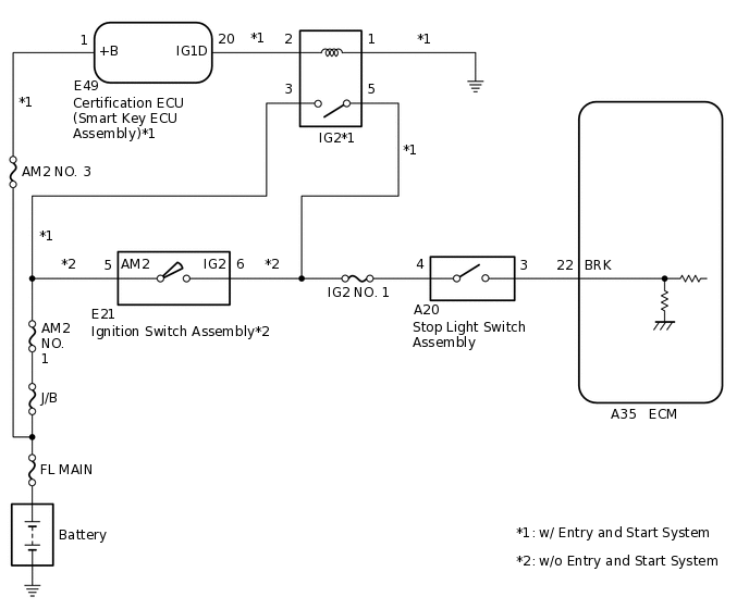
The stop light switch assembly is installed to the brake pedal. The stop light switch assembly detects the operation of the brake pedal and sends a signal to the ECM.
DTC No. |
Detection Item |
DTC Detection Condition |
Trouble Area |
MIL |
Memory |
|---|---|---|---|---|---|
P0504 |
Brake Switch "A" / "B" Correlation |
Stop light switch signals received by ECM via direct line communication and from skid control ECU via CAN communication do not match. |
|
Does not come on |
DTC stored |
P1536 |
Secondary Brake Information Sensor - Inconsistency in Deceleration or Invalid Signal |
Stop light switch signals received by ECM via direct line communication and from skid control ECU via CAN communication do not match. |
|
Does not come on |
DTC stored |
MONITOR DESCRIPTION
These DTCs are stored when a malfunction is detected in the stop light switch signal. If the stop light switch signals received from the stop light switch assembly via direct line and the skid control ECU via CAN communication do not match, the ECM will store a DTC.
WIRING DIAGRAM
PROCEDURE
INSPECT STOP LIGHT SWITCH ASSEMBLY
Inspect the stop light switch assembly.
Result
Proceed to
OK
NG
CHECK HARNESS AND CONNECTOR (STOP LIGHT SWITCH ASSEMBLY - ECM)
Disconnect the stop light switch assembly connector.
Disconnect the ECM connector.
Measure the resistance according to the value(s) in the table below.
Standard Resistance
Tester Connection
Condition
Specified Condition
A20-3 - A35-22 (BRK)
Always
Below 1 Ω
A20-3 or A35-22 (BRK) - Body ground and other terminals
Always
10 kΩ or higher
Result
Proceed to
OK
NG
NG REPAIR OR REPLACE HARNESS OR CONNECTOR
CHECK TERMINAL VOLTAGE (POWER SOURCE OF STOP LIGHT SWITCH ASSEMBLY)
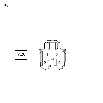
*a
Front view of wire harness connector
(to Stop Light Switch Assembly)
Disconnect the stop light switch assembly connector.
Turn the ignition switch to ON.
Measure the voltage according to the value(s) in the table below.
Standard Voltage
Tester Connection
Condition
Specified Condition
A20-4 - Body ground
Ignition switch ON
11 to 14 V
Result
Result
Proceed to
OK
A
NG (w/ Entry and Start System)
B
NG (w/o Entry and Start System)
C
B REPAIR OR REPLACE HARNESS OR CONNECTOR (STOP LIGHT SWITCH ASSEMBLY - IG2 RELAY)
C REPAIR OR REPLACE HARNESS OR CONNECTOR (STOP LIGHT SWITCH ASSEMBLY - IGNITION SWITCH ASSEMBLY)