ENGINE ASSEMBLY REMOVAL
PROCEDURE
-
PRECAUTION
CAUTION:
-
The engine assembly with transmission is very heavy. Be sure to follow the procedure described in the repair manual, or the engine lifter may suddenly drop.
-
The vehicle has a hybrid system that operates at voltages up to 650 V. The hybrid system uses an HV battery that contains an electrolyte which is a strong alkali solution that includes potassium hydroxide. Be sure to follow the instructions in this manual to handle the system correctly. Failure to do so may result in serious injury or electrocution Click here.
Note
After turning the power switch off, waiting time may be required before disconnecting the cable from the negative (-) auxiliary battery terminal. Therefore, make sure to read the disconnecting the cable from the negative (-) auxiliary battery terminal notices before proceeding with work Click here.
-
-
DISCHARGE FUEL SYSTEM PRESSURE
-
REMOVE SERVICE PLUG GRIP
-
ALIGN FRONT WHEELS FACING STRAIGHT AHEAD
-
REMOVE FRONT WHEEL
-
REMOVE REAR ENGINE UNDER COVER LH
-
REMOVE REAR ENGINE UNDER COVER RH
-
REMOVE FRONT LOWER BUMPER ABSORBER
-
REMOVE NO. 1 ENGINE UNDER COVER
-
REMOVE NO. 2 ENGINE UNDER COVER
-
DRAIN ENGINE OIL
-
DRAIN COOLANT (for Engine)
-
DRAIN COOLANT (for Inverter)
-
DRAIN HYBRID TRANSAXLE FLUID
-
REMOVE NO. 2 CYLINDER HEAD COVER
-
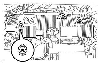
Remove the 3 clips and No. 2 cylinder head cover.
Note
-
Attempting to disengage both front and rear clips at the same time may cause the No. 2 cylinder cover to break.
-
Pull the No. 2 cylinder cover straight up to remove it. Attempting to pull the No. 2 cylinder cover forward may cause it to break.
-
-
-
REMOVE RADIATOR SUPPORT OPENING COVER
-
REMOVE AIR CLEANER CAP SUB-ASSEMBLY
-
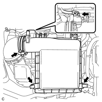
Disconnect the air flow meter connector.
-
Disconnect the 2 clamps and hose band, and remove the air cleaner cap sub-assembly.
-
Remove the air cleaner filter element.
-
-
REMOVE INLET AIR CLEANER ASSEMBLY
-
Remove the 2 bolts and inlet air cleaner assembly.
-
-
REMOVE AIR CLEANER CASE
-
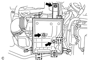
Separate the 3 clamps and No. 4 water by-pass hose from the air cleaner case.
-
Remove the 3 bolts and air cleaner case.
-
-
REMOVE AIR CLEANER HOSE ASSEMBLY
-
REMOVE NO. 1 INVERTER BRACKET
-
DISCONNECT ENGINE ROOM MAIN WIRE
-
REMOVE INVERTER COVER
-
CHECK TERMINAL VOLTAGE
-
DISCONNECT FRAME WIRE
-
DISCONNECT GENERATOR CABLE
-
DISCONNECT MOTOR CABLE
-
DISCONNECT NO. 2 ENGINE WIRE
-
INSTALL INVERTER COVER
-
DISCONNECT NO. 2 ENGINE ROOM WIRE
-
DISCONNECT WATER HOSE
-
REMOVE INVERTER WITH CONVERTER ASSEMBLY
-
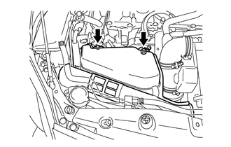
REMOVE INVERTER RESERVE TANK ASSEMBLY
-
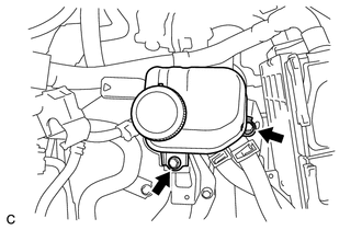
Remove the 2 bolts and inverter reserve tank assembly.
-
-
REMOVE INVERTER TRAY BRACKET
-
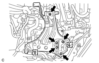
Separate the 2 clamps.
-
Remove the 5 bolts and inverter tray bracket.
-
-
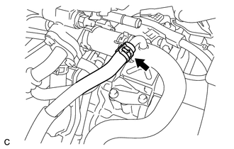
DISCONNECT NO. 1 RADIATOR HOSE
-
Slide the clamp and disconnect the No. 1 radiator hose from the radiator pipe.
-
-
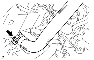
DISCONNECT NO. 2 RADIATOR HOSE
-
Slide the clamp and disconnect the No. 2 radiator hose from the water inlet.
-
-
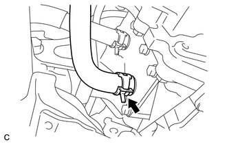
DISCONNECT NO. 4 WATER BY-PASS HOSE
-
Slide the clamp and disconnect the No. 4 water by-pass hose from the radiator pipe.
-
-
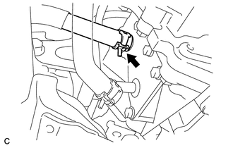
DISCONNECT NO. 3 INVERTER COOLING HOSE
-
Slide the clamp and disconnect the No. 3 inverter cooling hose from the hybrid vehicle transaxle assembly.
-
-
DISCONNECT NO. 5 INVERTER COOLING HOSE
-
Slide the clamp and disconnect the No. 5 inverter cooling hose from the hybrid vehicle transaxle assembly.
-
-
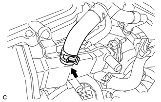
DISCONNECT OUTLET HEATER WATER HOSE
-
Slide the clamp and disconnect the outlet heater water hose.
-
-
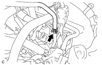
DISCONNECT INLET HEATER WATER HOSE
-
Slide the clamp and disconnect the inlet heater water hose.
-
-
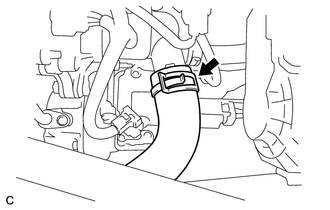
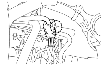
DISCONNECT HEATER HOSE
-
Slide the clamp and disconnect the heater hose.
-
-
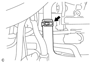
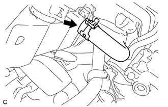
DISCONNECT NO. 1 FUEL VAPOR FEED HOSE
-
Slide the clamp and disconnect the No. 1 fuel vapor feed hose.
-
-
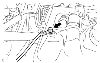
DISCONNECT FUEL TUBE SUB-ASSEMBLY
-
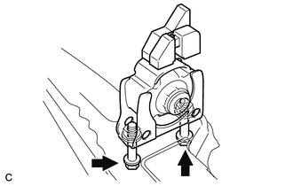
Release the claw and remove the No. 1 fuel pipe clamp.
-
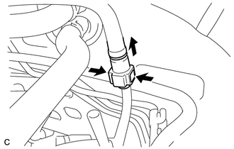
Pinch the retainer as illustrated, then pull the fuel tube connector out of the pipe.
Note
-
Remove any dirt and foreign matter from the fuel tube connector before performing this work.
-
Do not allow any scratches or foreign matter to get on the parts when disconnecting, as the fuel tube connector has the O-rings that seal the pipe.
-
Perform this work by hand. Do not use any tools.
-
Do not forcibly bend, kink or twist the nylon tube.
-
Protect the disconnected parts by covering them with plastic bags after disconnecting the fuel tube.
-
If the fuel tube connector and pipe are stuck, push and pull to release them.
-
-
-
SEPARATE COMPRESSOR WITH MOTOR ASSEMBLY
-
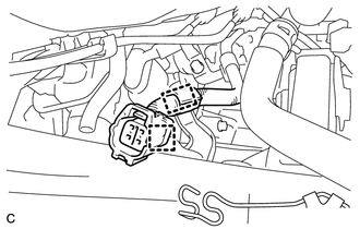
DISCONNECT ENGINE WIRE
-
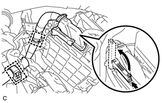
Disconnect the 2 clamps.
-
Pull up the lever and disconnect the ECM connector.
-
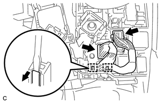
Disconnect the 2 connectors, 2 clamps and engine wire from the engine room junction block.
-
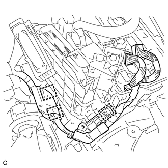
Disconnect the 3 clamps.
-
Remove the bolt and disconnect the earth wire.
-
Disconnect the 2 clamps and engine wire.
-
-
SECURE STEERING WHEEL
-
REMOVE COLUMN HOLE COVER SILENCER SHEET (for LHD)
-
SEPARATE NO. 2 STEERING INTERMEDIATE SHAFT ASSEMBLY (for LHD)
-
DISCONNECT NO. 1 STEERING COLUMN HOLE COVER SUB-ASSEMBLY
-
REMOVE FRONT NO. 3 ENGINE UNDER COVER
-
REMOVE FRONT CENTER FLOOR BRACE
-
REMOVE FRONT EXHAUST PIPE ASSEMBLY (w/ Exhaust Heat Recirculation System)
-
REMOVE FRONT EXHAUST PIPE ASSEMBLY (w/o Exhaust Heat Recirculation System)
-
REMOVE FRONT AXLE SHAFT NUT LH
-
REMOVE FRONT AXLE SHAFT NUT RH
Tech Tips
Perform the same procedure as for the LH side.
-
SEPARATE FRONT SPEED SENSOR LH
-
SEPARATE FRONT SPEED SENSOR RH
Tech Tips
Perform the same procedure as for the LH side.
-
SEPARATE TIE ROD END SUB-ASSEMBLY LH
-
SEPARATE TIE ROD END SUB-ASSEMBLY RH
Tech Tips
Perform the same procedure as for the LH side.
-
SEPARATE FRONT STABILIZER LINK ASSEMBLY LH
-
SEPARATE FRONT STABILIZER LINK ASSEMBLY RH
Tech Tips
Perform the same procedure as for the LH side.
-
SEPARATE FRONT LOWER NO. 1 SUSPENSION ARM SUB-ASSEMBLY LH
-
SEPARATE FRONT NO. 1 LOWER SUSPENSION ARM SUB-ASSEMBLY RH
Tech Tips
Perform the same procedure as for the LH side.
-
SEPARATE FRONT DRIVE SHAFT ASSEMBLY LH
-
REMOVE FRONT DRIVE SHAFT ASSEMBLY LH
-
SEPARATE FRONT DRIVE SHAFT ASSEMBLY RH
Tech Tips
Perform the same procedure as for the LH side.
-
REMOVE FRONT DRIVE SHAFT ASSEMBLY RH
Tech Tips
Perform the same procedure as for the LH side.
-
REMOVE FRONT DRIVE SHAFT HOLE SNAP RING LH
-
REMOVE FRONT DRIVE SHAFT HOLE SNAP RING RH
Tech Tips
Perform the same procedure as for the LH side.
-
REMOVE FRONT LOWER ENGINE MOUNTING BRACKET REINFORCEMENT
-
REMOVE REAR SIDE RAIL REINFORCEMENT SUB-ASSEMBLY LH
-
REMOVE REAR SIDE RAIL REINFORCEMENT SUB-ASSEMBLY RH
-
REMOVE FRONT SUSPENSION MEMBER REAR BRACE LH
-
REMOVE FRONT SUSPENSION MEMBER REAR BRACE RH
Tech Tips
Perform the same procedure as for the LH side.
-
REMOVE FRONT SUSPENSION CROSSMEMBER SUB-ASSEMBLY
-
REMOVE ENGINE ASSEMBLY WITH TRANSAXLE
-
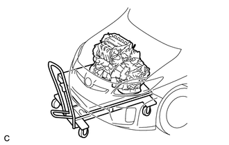
Set an engine lifter.
Note
Place the engine assembly on wooden blocks or equivalent so that the engine assembly is level.
-
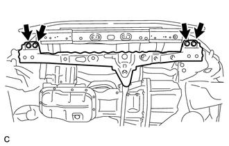
Remove the 4 bolts and separate the front crossmember sub-assembly.
-
Remove the bolt and 2 nuts, and separate the engine mounting insulator sub-assembly RH.
-
Remove the bolt and nut, and separate the engine mounting insulator LH.
-
Carefully remove the engine assembly with transaxle from the vehicle.
-
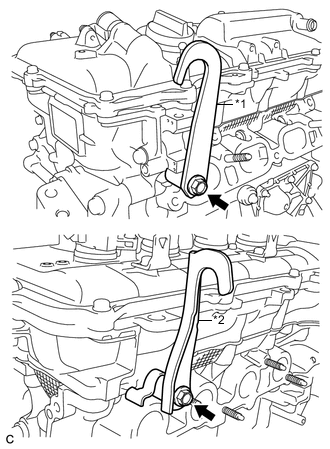
Text in Illustration *1 No. 1 Engine Hanger *2 No. 2 Engine Hanger Install the No. 1 engine hanger and No. 2 engine hanger with the 2 bolts.
- Torque:
- 43 N*m { 438 kgf*cm, 32 ft.*lbf }
Part Name Part No. No. 1 engine hanger 12281-37021 No. 2 engine hanger 12282-37011 Bolt 91552-81050 -
Attach an engine sling device and hang the engine assembly with a chain block.
-
-
REMOVE FRONT CROSSMEMBER SUB-ASSEMBLY
-
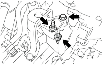
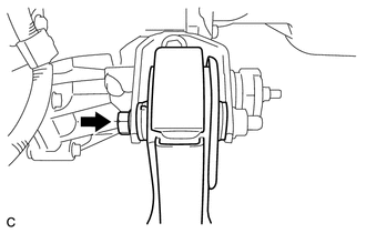
Remove the bolt and nut, and separate the front engine mounting insulator from the front engine mounting bracket.
-
-
REMOVE FRONT ENGINE MOUNTING INSULATOR
Tech Tips
Perform this procedure only when replacement of the front engine mounting insulator is necessary.
-
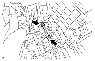
Remove the 2 bolts and front engine mounting insulator.
-
-
REMOVE REAR ENGINE MOUNTING INSULATOR
Tech Tips
Perform this procedure only when replacement of the rear engine mounting insulator is necessary.
-
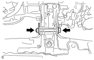
Remove the through bolt and rear engine mounting insulator.
-
-
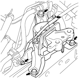
REMOVE ENGINE MOUNTING INSULATOR LH
Tech Tips
Perform this procedure only when replacement of the engine mounting insulator LH is necessary.
-
Remove the 4 bolts and engine mounting insulator LH.
-
-
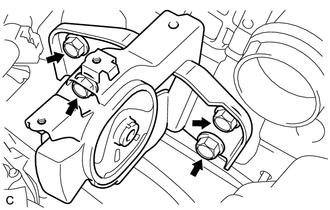
REMOVE ENGINE MOUNTING INSULATOR SUB-ASSEMBLY RH
Tech Tips
Perform this procedure only when replacement of the engine mounting insulator sub-assembly RH is necessary.
-
Remove the 2 bolts and 2 cooler brackets.
-
Disconnect the earth wire clamp from the engine mounting insulator sub-assembly RH.
-
Remove the 3 bolts and engine mounting insulator sub-assembly RH.
-
-
REMOVE RADIATOR PIPE
-
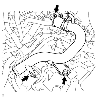
Slide the clamp and remove the No. 3 radiator hose from the cylinder head.
-
Remove the 2 bolts and radiator pipe.
-
-
REMOVE STARTER HOLE INSULATOR
-
REMOVE FLYWHEEL HOUSING SIDE COVER
-
REMOVE ENGINE WIRE
-
Disconnect all the wire harnesses and connectors. Make sure that no wire harnesses are connected to the engine assembly.
-
-
REMOVE HYBRID VEHICLE TRANSAXLE ASSEMBLY
-
Remove the hybrid vehicle transaxle assembly Click here.
Note
Be careful not to apply excessive force to the transmission input damper assembly when removing or installing the hybrid vehicle transaxle assembly. If excessive force is applied, the transmission input damper assembly may be damaged, or its splines may become misaligned.
-
-
REMOVE TRANSMISSION INPUT DAMPER ASSEMBLY
-
Gently place the engine assembly onto wood blocks or equivalent.
Note
This step should be done while hanging the engine assembly using the engine hangers and a chain block.
-
Remove the transmission input damper assembly Click here.
-
-
REMOVE FLYWHEEL SUB-ASSEMBLY
-
Remove the flywheel sub-assembly Click here.
-