AIR CONDITIONING SYSTEM PTC Heater Circuit
DESCRIPTION
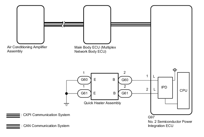
The air conditioning amplifier assembly sends operation signals to the PTC heater relays when quick heater assembly operation conditions are met. Based on the signals from the air conditioning amplifier assembly, the PTC heater relays turn on, and power is supplied to the quick heater assembly installed in the air conditioning radiator assembly.
| Symptom | Factor |
|---|---|
| Heating performance is poor when it is cold. |
|
WIRING DIAGRAM
CAUTION / NOTICE / HINT
Note
If the battery voltage is low, the PTC heater may not operate. When "Operation of Electrical Items Restricted." is displayed on the multi-information display in the combination meter assembly, inspect the battery, referring to On-vehicle Inspection for the charging system.
Tech Tips
If the battery voltage is low, the PTC heater may not operate. When "Operation of Electrical Items Restricted." is not displayed on the multi-information display in the combination meter assembly, check the Data List item "Battery Control Count (Body ECU)".
PROCEDURE
-
CHECK CAN COMMUNICATION SYSTEM
-
Using the GTS, check if the CAN communication system is functioning normally.
OK CAN communication system DTCs are not output. Result Proceed to OK NG
NG 
GO TO CAN COMMUNICATION SYSTEM Click here
OK 
-
-
CHECK CXPI COMMUNICATION SYSTEM
-
Using the GTS, check if the CXPI communication system is functioning normally.
OK CXPI communication system DTCs are not output. Result Proceed to OK NG
NG
GO TO CXPI COMMUNICATION SYSTEM Click here
OK
-
-
CHECK POWER INTEGRATION SYSTEM
-
Using the GTS, check if the power integration system is functioning normally.
OK Power integration system DTCs are not output. Result Proceed to OK NG
NG
GO TO POWER INTEGRATION SYSTEM Click here
OK
-
-
CHECK QUICK HEATER ASSEMBLY
-
Disconnect the quick heater assembly connectors.
-
Connect the GTS to the DLC3.
-
Turn the engine switch on (IG).
-
Turn the GTS on.
-
Enter the following menus: Body Electrical / Air Conditioner / Active Test.
-
Perform the Active Test according to the display on the GTS.
Body Electrical > Air Conditioner > Active TestTester Display Measurement Item Control Range Restrict Condition Heater Active Level Quick heater assembly Min.: 0
Max.: 2
Perform this test when the following conditions are met:
-
Engine switch on (IG)
-
Air conditioning system is operated
Body Electrical > Air Conditioner > Active TestTester Display Heater Active Level -
-
Measure the voltage according to the value(s) in the table below.
Standard Voltage Tester Connection Condition Specified Condition G60-2 (B) - Body ground
-
Perform Active Test and select "OFF" → "ON" item
-
Heater level is 1
Below 1 V → 11 to 14 V G61-2 (B) - Body ground
-
Perform Active Test and select "OFF" → "ON" item
-
Heater level is 2
Below 1 V → 11 to 14 V Result Proceed to OK NG -
NG 
CHECK HARNESS AND CONNECTOR (QUICK HEATER ASSEMBLY - NO. 2 SEMICONDUCTOR POWER INTEGRATION ECU AND BODY GROUND) Click here
OK
-
-
CHECK HARNESS AND CONNECTOR (QUICK HEATER ASSEMBLY - BODY GROUND)
-
Disconnect the quick heater assembly connectors.
-
Measure the resistance according to the value(s) in the table below.
Standard Resistance Tester Connection Condition Specified Condition G60-1 (E) - Body ground Always Below 1 Ω G61-1 (E) - Body ground Always Below 1 Ω Result Proceed to OK NG
NG
REPAIR OR REPLACE HARNESS OR CONNECTOR
OK
-
-
INSPECT QUICK HEATER ASSEMBLY
-
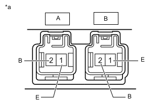
*a Component without harness connected
(Quick Heater Assembly)
Disconnect the quick heater assembly connectors.
-
Measure the resistance according to the value(s) in the table below.
Standard Resistance Tester Connection Condition Specified Condition A-2 (B) - A-1 (E) Always Below 10 kΩ B-2 (B) - B-1 (E) Always Below 10 kΩ Result Proceed to OK NG
OK
USE SIMULATION METHOD TO CHECK Click here
NG
REPLACE QUICK HEATER ASSEMBLY Click here
-
-
CHECK HARNESS AND CONNECTOR (QUICK HEATER ASSEMBLY - NO. 2 SEMICONDUCTOR POWER INTEGRATION ECU AND BODY GROUND)
-
Disconnect the G60 and G61 quick heater assembly connectors.
-
Disconnect the G97 No. 2 semiconductor power integration ECU connector.
-
Measure the resistance according to the value(s) in the table below.
Standard Resistance Tester Connection Condition Specified Condition G60-2 (B) - G97-1 (L) - Other terminals and body ground Always 10 kΩ or higher G61-2 (B) or G97-2 (L) - Other terminals and body ground Always 10 kΩ or higher Result Proceed to OK NG
NG
REPAIR OR REPLACE HARNESS OR CONNECTOR
OK
-
-
READ VALUE USING GTS (STATUS OF PTC HEATER NO.1 FUSE, STATUS OF PTC HEATER NO.2 FUSE)
-
Connect the GTS to the DLC3.
-
Turn the engine switch on (IG).
-
Turn the GTS on.
-
Enter the following menus: Body Electrical / Power Integration No.1 / Data List.
-
Read the Data List according to the display on the GTS.
Body Electrical > Power Integration No.2 > Data ListTester Display Measurement Item Range Normal Condition Diagnostic Note Status of PTC Heater No.1 Fuse Quick heater assembly fuse Connect or Disconnect Connect: Fuse not shut off
Disconnect: Fuse shut off
- Status of PTC Heater No.2 Fuse Quick heater assembly fuse Connect or Disconnect Connect: Fuse not shut off
Disconnect: Fuse shut off
-
Body Electrical > Power Integration No.2 > Data ListTester Display Status of PTC Heater No.1 Fuse Status of PTC Heater No.2 Fuse OK The Data List value displays "Connect". Result Proceed to OK NG
OK
REPLACE NO. 2 SEMICONDUCTOR POWER INTEGRATION ECU Click here
NG
REPLACE NO. 2 SEMICONDUCTOR POWER INTEGRATION ECU AND QUICK HEATER ASSEMBLY No. 2 semiconductor power integration ECU: Click here Quick heater assembly: Click here
-