TIRE AND WHEEL SYSTEM INSPECTION
PROCEDURE
-
INSPECT TIRES
-
Check the tires for wear and proper inflation pressure.
Cold Tire Inflation Pressure Tire Size Front
kPa (kgf/cm2, psi)
Rear
kPa (kgf/cm2, psi)
205/60R16 92V 250 (2.5, 36)
240 (2.4, 35)*1
250 (2.5, 36)
230 (2.3, 33)*1
215/50R17 91V 230 (2.3, 33) 230 (2.3, 33) *1: for Australia
-
Perform initialization (w/ Tire Pressure Warning System) Click here.
-
Tire pressure adjustment method when warm (w/ Tire Pressure Warning System).
-
Turn the power switch off.
-
Connect the GTS to the DLC3.
-
Turn the power switch on (IG).
-
Turn the GTS on.
-
Enter the following menus: Chassis / Tire Pressure Monitor / Data List.
-
Adjust the tire pressure so that the displayed value is equal to the set pressure.
-
Perform initialization and check that initialization completes Click here.
-
Check and record the value of the Data List item "Temperature in Tire". (Ts)
-
Check and record the ambient temperature during tire pressure adjustment. (Tm)
-
Readjust the tire pressure according to the difference between the tire internal temperature (Ts) and the ambient temperature (Tm). (P)
Tech Tips
Tire internal temperature: Ts, Ambient temperature: Tm, Tire pressure readjustment value: P
P = (Specified Pressure) + (Ts - Tm)
-
Check the pressure adjustment value with the Data List item "Tire Inflation Pressure".
Note
for ECE-R64 Type:If the tire pressure is decreased approximately 20 kPa (0.2 kgf/cm2, 2.9 psi) or more in order to adjust the tire pressure, even if the adjusted tire pressure is 80% or more than the tire pressure set during system initialization, the tire pressure warning light may illuminate if the tire pressure drops below 80% of the tire pressure set when the tires are warmed. In this case, perform initialization again.
-
-
-
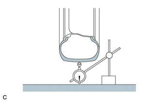
Using a dial indicator, check the runout of the tires.
Maximum Tire Runout 1.4 mm (0.0551 in.)
-
-
ROTATE TIRES
-
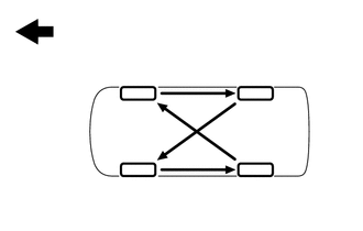
Rotate the tires as shown in the illustration.
Text in Illustration 
Front -
Perform initialization (w/ Tire Pressure Warning System) Click here.
-
-
INSPECT AND ADJUST WHEEL BALANCE
-
Inspect and adjust the off-the-car balance.
Maximum Imbalance 8.0 g (0.0176 lb) Note
-
Use a cleaning detergent to remove dirt, oil and water from the surface where the balance weight is to be adhered.
-
Do not touch the adhesive surface of the balance weight.
-
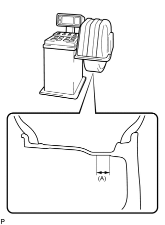
Adhere a stick-on type balance weight to the flat surface (A) shown in the illustration.
Width (A) 25 mm (0.984 in.) -
Push the balance weight securely with your finger to adhere it to the desired position.
-
Do not reuse balance weights.
Tech Tips
The inner side balance weight should be installed by clipping it to the rim.
-
-
-
INSPECT FRONT AXLE HUB AND BEARING
-
INSPECT REAR AXLE HUB AND BEARING