METER / GAUGE SYSTEM Entire Combination Meter does not Operate
| DTC Code | DTC Name |
|---|---|
| Entire Combination Meter does not Operate |
DESCRIPTION
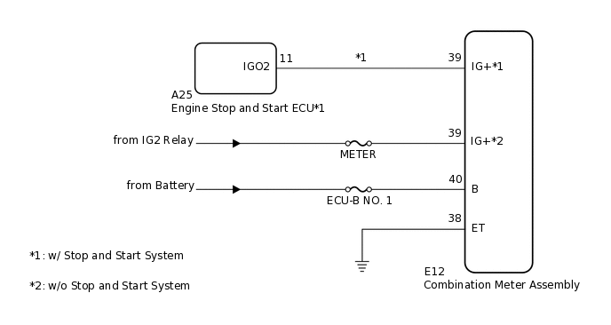
This circuit is the power source circuit for the combination meter assembly. This circuit provides two types of power sources; one is a constant power source, and the other is an IG power source.
WIRING DIAGRAM
CAUTION / NOTICE / HINT
Inspect the fuses of circuits related to this system before performing the following procedure.
When it is necessary to replace the combination meter assembly, be sure to replace it with a new one.
PROCEDURE
CONFIRM VEHICLE TYPE
Choose the model to be inspected.
Result
Result
Proceed to
w/ Stop and Start System
A
w/o Stop and Start System
B
B CHECK HARNESS AND CONNECTOR (COMBINATION METER ASSEMBLY - BODY GROUND)Click here
CHECK FOR DTC
Check if stop and start system DTCs are output.
Result
Result
Proceed to
Stop and start system DTCs are not output.
A
Stop and start system DTCs are output.
B
CHECK HARNESS AND CONNECTOR (COMBINATION METER ASSEMBLY - BODY GROUND)
Disconnect the E12 combination meter assembly connector.
Measure the resistance according to the value(s) in the table below.
Standard Resistance
Tester Connection
Condition
Specified Condition
E12-38 (ET) - Body ground
Always
Below 1 Ω
Measure the voltage according to the value(s) in the table below.
Standard Voltage
Tester Connection
Condition
Specified Condition
E12-39 (IG+) - Body ground*
Ignition switch off
Below 1 V
Ignition switch ON
11 to 14 V
E12-40 (B) - Body ground
Always
11 to 14 V
*: w/o Stop and Start System
Result
Proceed to
OK
NG
NG REPAIR OR REPLACE HARNESS OR CONNECTOR