BRAKE CONTROL SYSTEM
-
CONSTRUCTION
-
The brake booster pump assembly consists of a pump, accumulator and pump motor.
-
High pressure nitrogen gas is charged and sealed within the accumulator. A formed metal bellows is used in order to prevent possible discharge of the nitrogen gas.
-
A plunger type pump is used. This pump is operated by the rotation of a motor driven cam, to supply high-pressure fluid to the accumulator.
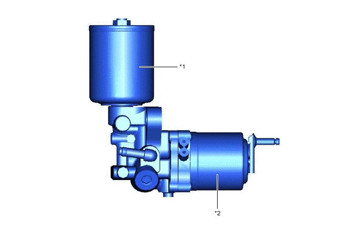
*1 Accumulator *2 Pump Motor -
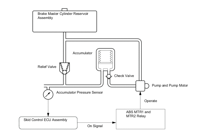
Operation of Brake Booster Pump Assembly
-
The brake fluid that is discharged by the pump passes through the check valve and is stored in the accumulator. The hydraulic pressure that is stored in the accumulator is used for providing the hydraulic pressure that is needed for normal braking and for operating the brake control.
-
The pump motor is actuated by relays ABS MTR1 and MTR2 which are controlled by signals from the skid control ECU assembly.
-
The accumulator pressure sensor constantly monitors the pressure in the accumulator and transmits it to the skid control ECU assembly. If the accumulator pressure drops below the set pressure, the skid control ECU assembly sends an activation signal to the motor relay in order to actuate the pump motor until the pressure in the accumulator reaches the set pressure.
-
If the pump and the pump motor continue to operate unintentionally, such as during a failure of the accumulator sensor, excessive pressure will build up in the accumulator. At this time, the relief valve will open to return the brake fluid to the reservoir tank, to limit the accumulator pressure.

-
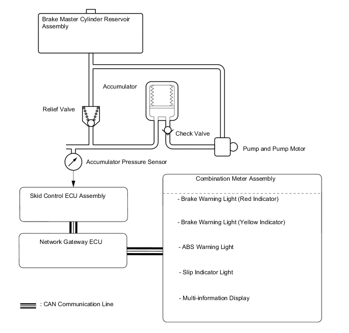
If the accumulator pressure drops abnormally to a level below the pressure set at the ECU, the skid control ECU assembly illuminates the brake system warning light (red indicator), brake system warning light (yellow indicator), ABS warning light and slip indicator light. Then, a warning message appears on the multi-information display.
-
-