MANUAL TRANSAXLE UNIT DISASSEMBLY

PROCEDURE
-
REMOVE MANUAL TRANSMISSION FILLER PLUG
-
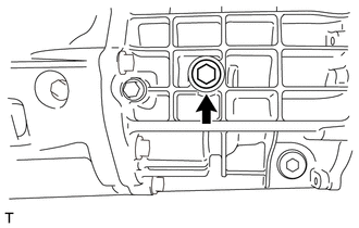
Remove the manual transmission filler plug and gasket.
-
-
REMOVE MANUAL TRANSMISSION DRAIN PLUG
-
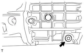
Remove the manual transmission drain plug and gasket.
-
-
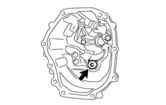
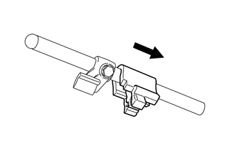
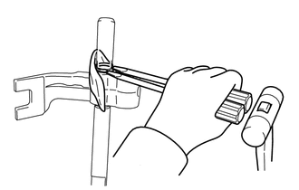
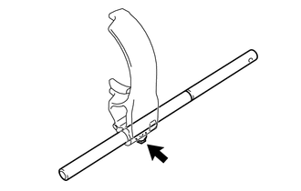
REMOVE RELEASE FORK SUPPORT
-
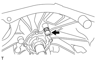
Using a 19 mm deep socket wrench, remove the release fork support from the clutch housing.
-
-
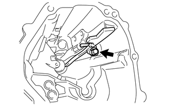
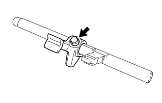
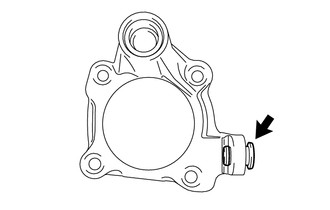
REMOVE BACK-UP LIGHT SWITCH ASSEMBLY
-
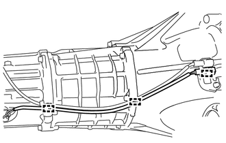
Disengage the 3 clamps.
-
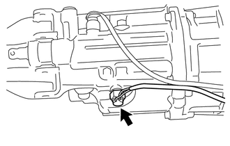
Using a 19 mm union nut wrench, remove the back-up light switch assembly and gasket.
-
-
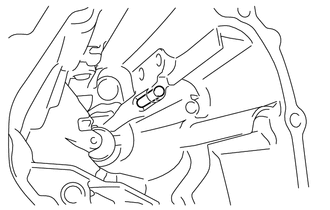
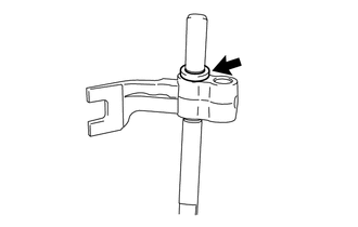
REMOVE NEUTRAL POSITION SWITCH ASSEMBLY
-
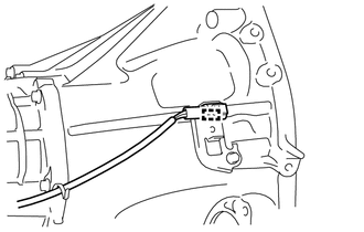
Disengage the clamp.
-
Using a 19 mm union nut wrench, remove the neutral position switch assembly and gasket.
-
-
REMOVE WIRE HARNESS CLAMP BRACKET
-
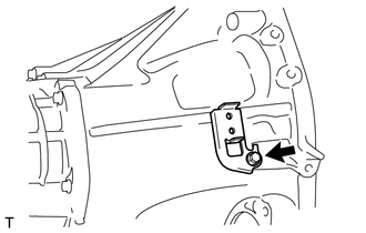
Remove the bolt and wire harness clamp bracket.
-
-
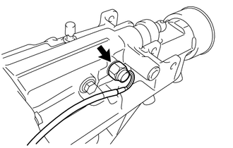
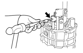
REMOVE LOCK BALL PIN
-
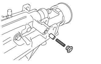
Using a 10 mm hexagon socket wrench, remove the head straight screw plug, compression spring and lock ball pin.
-
-
REMOVE HOLDER
-
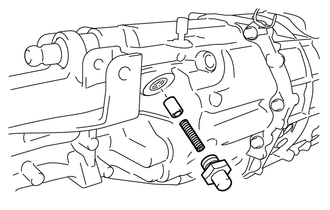
Using a 27 mm deep socket wrench, remove the holder, compression spring and lock ball pin.
-
-
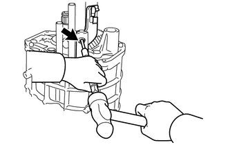
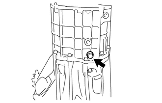
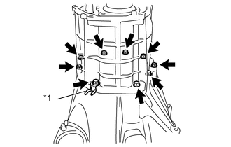
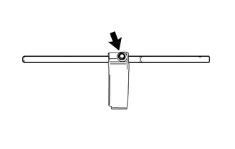
REMOVE TRANSMISSION EXTENSION HOUSING SUB-ASSEMBLY
-
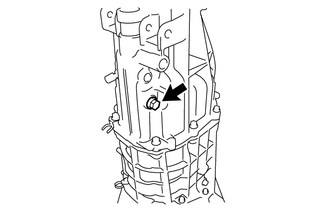
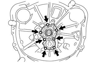
Remove the bolt.
-
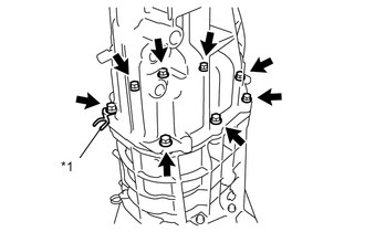
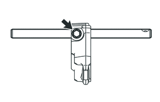
Text in Illustration *1 Clamp Remove the 8 bolts and clamp.
-
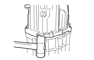
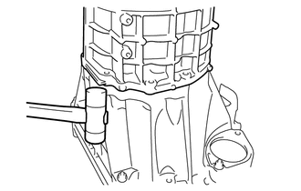
Using a plastic hammer, remove the transmission extension housing sub-assembly.
Note
-
Be sure to remove the transmission extension housing sub-assembly while the transmission is in neutral.
-
Do not damage the transmission extension housing sub-assembly.
-
-
-
REMOVE EXTENSION HOUSING REAR OIL SEAL
-
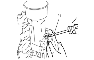
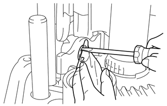
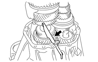
Text in Illustration *1 Protective Tape Using a screwdriver with its tip wrapped with protective tape, remove the extension housing rear oil seal.
Note
Do not damage the transmission extension housing sub-assembly.
Tech Tips
Remove the transmission extension housing sub-assembly while protecting it with a piece of cloth.
-
-
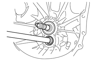
REMOVE EXTENSION HOUSING DUST DEFLECTOR
-
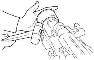
Using a plastic hammer, remove the extension housing dust deflector.
-
-
REMOVE TRANSMISSION EXTENSION HOUSING OIL SEAL
-
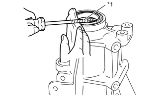
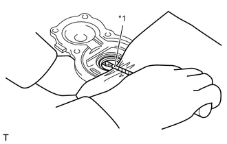
Text in Illustration *1 Protective Tape Using a screwdriver with its tip wrapped with protective tape, remove the transmission extension housing oil seal.
Note
Do not damage the transmission extension housing sub-assembly.
Tech Tips
Remove the transmission extension housing sub-assembly while protecting it with a piece of cloth.
-
-
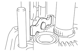
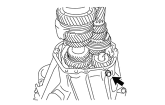
REMOVE NO. 2 EXTENSION HOUSING OIL RECEIVER PIPE
-
Remove the No. 2 extension housing oil receiver pipe.
-
-
REMOVE NO. 1 EXTENSION HOUSING OIL RECEIVER PIPE
-
Remove the bolt, No. 1 extension housing oil receiver pipe and stopper plate.
-
Remove the straight pin.
-
-
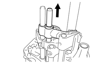
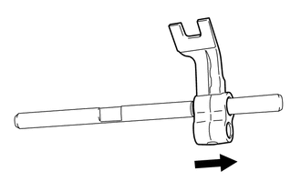
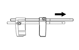
REMOVE SHIFT SHAFT
-
Slide and remove the shift shaft and No. 1 shift inter lock block.
-
-
REMOVE NO. 1 SHIFT INTER LOCK BLOCK
-
Remove the No. 1 shift inter lock block from the shift shaft.
-
-
REMOVE FRONT SHIFT INNER LEVER
-
Remove the bolt and front shift inner lever from the shift shaft.
-
-
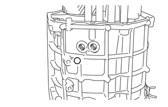
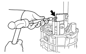
REMOVE HEAD STRAIGHT SCREW PLUG
-
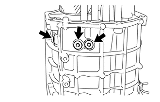
Using a T40 "TORX" socket wrench, remove 3 head straight screw plugs.
-
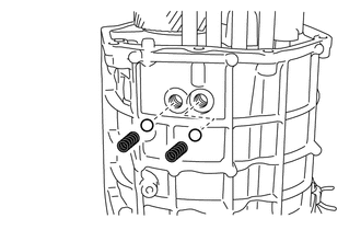
Using a magnet hand, remove the 2 compression springs and 2 balls.
-
-
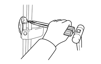
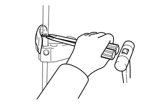
REMOVE SHIFT ARM
-
Using a screwdriver, remove the E-ring.
Note
Use a cloth to prevent the E-ring from flying off.
-
Remove the shift arm.
-
-
REMOVE NO. 3 GEAR SHIFT FORK SHAFT
-
Remove the No. 3 gear shift fork shaft and 5th shift head together.
Note
-
Be careful not to drop the ball from the 5th shift head.
-
The ball on the transmission case may fall inside the transmission case. If that happens, take it out when the transmission case is removed.
-
-
Remove the ball from the 5th shift head.
-
Using a magnetic hand, remove the ball.
-
-
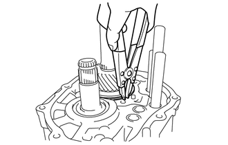
REMOVE 5TH SHIFT HEAD
-
Using 2 screwdrivers and a plastic hammer, remove the shaft snap ring.
Note
Use a cloth to prevent the shaft snap ring from flying off.
-
Remove the washer.
-
Remove the 5th shift head, compression spring and ball.
Note
Be careful of the ball and compression spring that fall out when sliding the 5th shift head.
-
-
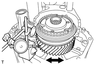
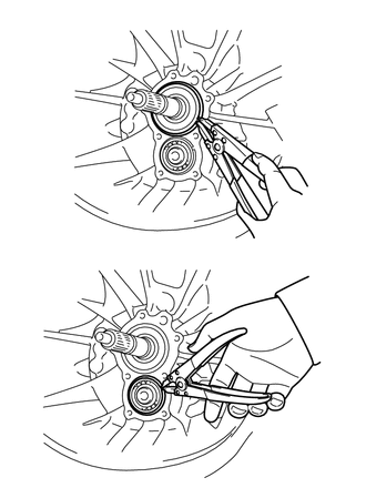
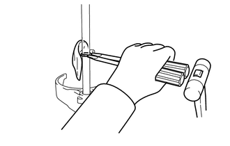
INSPECT COUNTER SHAFT 6TH GEAR THRUST CLEARANCE
-
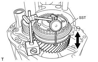
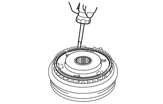
Using SST and a dial indicator, measure the thrust clearance.
- SST
- 09350-20015 ( 09350-06120 )
Standard clearance 0.10 to 0.40 mm (0.00394 to 0.0157 in.) Maximum clearance 0.40 mm (0.0157 in.) Tech Tips
If the clearance exceeds the maximum, replace the counter shaft 6th gear, No. 4 transmission clutch hub, 6th gear thrust washer, needle roller bearing and counter shaft with a new ones.
-
-
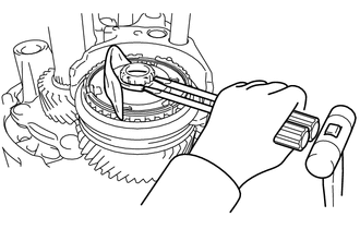
INSPECT COUNTER SHAFT 6TH GEAR RADIAL CLEARANCE
-
Using a dial indicator, measure the radial clearance.
Standard clearance 0.015 to 0.068 mm (0.000590 to 0.00268 in.) Maximum clearance 0.068 mm (0.00268 in.) Tech Tips
If the clearance exceeds the maximum, replace the counter shaft 6th gear, needle roller bearing and counter shaft with a new ones.
-
-
REMOVE NO. 4 TRANSMISSION CLUTCH HUB
-
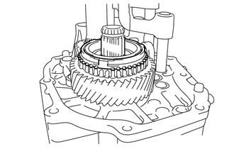
Using 2 screwdrivers and a plastic hammer, remove the shaft snap ring.
Note
Use a cloth to prevent the shaft snap ring from flying off.
-
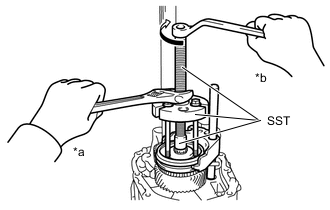
Text in Illustration *a Hold *b Turn Using SST and 3 bolts, remove the No. 4 transmission clutch hub, No.4 transmission hub sleeve, No. 4 gear shift fork and No. 2 gear shift fork shaft all together.
- SST
- 09950-30012 ( 09951-03010, 09953-03010, 09956-03010 )
-
-
REMOVE NO. 4 GEAR SHIFT FORK
-
for Pin:
-
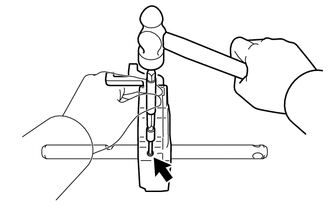
Using a 5 mm pin punch and hammer, remove the slotted spring pin.
-
Remove the No. 4 gear shift fork from the No. 2 gear shift fork shaft.
-
-
for Bolt:
-
Remove the bolt and No. 4 gear shift fork from the No. 2 gear shift fork shaft.
-
-
-
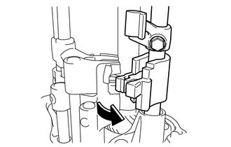
REMOVE NO. 4 TRANSMISSION HUB SLEEVE
-
Using a screwdriver, remove the hole snap ring.
-
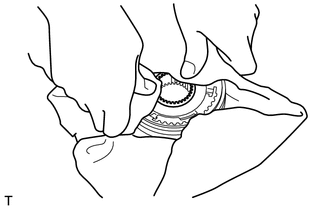
Remove the No. 4 transmission hub sleeve, and then remove the 3 No. 1 synchromesh shifting keys, 3 No. 1 synchromesh shifting key springs and 3 balls from the No. 4 transmission clutch hub.
Note
-
Use a cloth to prevent the No. 1 synchromesh shifting keys, No. 1 synchromesh shifting key springs and balls from popping out.
-
Do not deform the No. 1 synchromesh shifting key spring.
Tech Tips
During this operation, keep intact the No. 4 transmission clutch hub and No. 1 synchromesh shifting key.
-
-
-
REMOVE NO. 2 SYNCHRONIZER RING
-
Remove the No. 2 synchronizer ring.
-
-
REMOVE COUNTER SHAFT 6TH GEAR
-
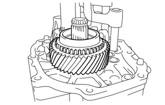
Remove the counter shaft 6th gear.
-
-
REMOVE NEEDLE ROLLER BEARING
-
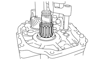
Remove the needle roller bearing.
-
-
REMOVE 6TH GEAR THRUST WASHER
-
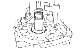
Remove the 6th gear thrust washer.
-
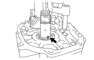
Remove the straight pin.
-
-
REMOVE NO. 2 GEAR SHIFT HEAD
-
Using a 5 mm pin punch and hammer, remove the slotted spring pin.
Note
-
Use a cloth to prevent the slotted spring pin from flying off.
-
Take care in order that the slotted spring pin does not fall inside through the gear shift fork shaft hole.
-
-
Remove the No. 2 gear shift head from the No. 2 gear shift fork shaft.
-
-
REMOVE NO. 1 GEAR SHIFT HEAD
-
Using a 5 mm pin punch and a hammer, remove the slotted spring pin.
Note
-
Use a cloth to prevent the slotted spring pin from flying off.
-
Take care in order that the slotted spring pin does not fall inside through the gear shift fork shaft hole.
-
-
Remove the No. 1 gear shift head from the No. 1 gear shift fork shaft.
-
-
REMOVE NO. 3 GEAR SHIFT HEAD
-
Using a 5 mm pin punch and a hammer, remove the slotted spring pin.
Note
-
Use a cloth to prevent the slotted spring pin from flying off.
-
Take care in order that the slotted spring pin does not fall inside through the gear shift fork shaft hole.
-
-
Remove the No. 3 gear shift head from the No. 3 gear shift fork shaft.
-
-
REMOVE REAR BEARING RETAINER
-
Using a T45 "TORX" socket wrench, remove the 4 bolts and rear bearing retainer.
-
Remove the shift arm pivot.
-
-
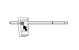
REMOVE TRANSMISSION CASE
-
Using a snap ring expander, remove the shaft snap ring.
-
Remove the bolt that retains the reverse idler gear shaft, and the gasket (transmission case side)
-
Text in Illustration *1 Clamp Remove the 9 bolts and clamp.
-
Using a plastic hammer, remove the transmission case.
Note
Do not damage the transmission case.
-
-
REMOVE OIL RECEIVER PIPE
-
Remove the oil receiver pipe.
-
-
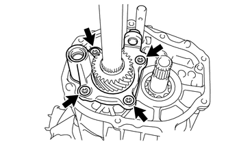
REMOVE FRONT BEARING RETAINER
-
Remove 7 bolts and front bearing retainer.
-
-
REMOVE TRANSMISSION FRONT BEARING RETAINER OIL SEAL
-
Text in Illustration *1 Protective Tape Using a screwdriver with its tip wrapped with protective tape, remove the transmission front bearing retainer oil seal.
Note
Do not damage the front bearing retainer.
Tech Tips
Remove the front bearing retainer while protecting it with a piece of cloth.
-
-
REMOVE COUNTER SHAFT
-
Using a snap ring expander, remove the 2 shaft snap rings.
Tech Tips
Remove the 2 shaft snap rings from the input shaft and counter shaft.
-
Remove the bolt and gasket to free the reverse idler gear and reverse idler gear shaft. (Clutch housing side)
-
Using a hammer handle edge, tap to remove the input shaft, output shaft, counter shaft, reverse idler gear, reverse idler gear shaft, No. 1 gear shift fork shaft, No. 2 gear shift fork shaft and No. 3 gear shift fork shaft all together from the clutch housing side.
-
-
REMOVE NO. 2 GEAR SHIFT FORK SHAFT
-
Using 2 screwdrivers and a plastic hammer, remove the shaft snap ring.
Note
Use a cloth to prevent the shaft snap ring from flying off.
-
Remove the bolt and No. 2 gear shift fork shaft.
-
-
REMOVE NO. 1 GEAR SHIFT FORK SHAFT
-
Using 2 screwdrivers and a plastic hammer, remove the shaft snap ring.
Note
Use a cloth to prevent the shaft snap ring from flying off.
-
Remove the No. 1 gear shift fork shaft and No.1 gear shift fork together.
-
Using 2 screwdrivers and a plastic hammer, remove the shaft snap ring.
Note
Use a cloth to prevent the shaft snap ring from flying off.
-
Remove the bolt and No. 1 gear shift fork shaft.
-
-
REMOVE NO. 3 GEAR SHIFT FORK SHAFT
-
Remove the bolt and No. 3 gear shift fork shaft.
-
-
REMOVE INPUT SHAFT
-
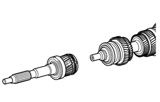
Remove the input shaft from the output shaft.
-
-
INSPECT REVERSE IDLER GEAR RADIAL CLEARANCE
-
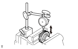
Use a vice to secure the reverse idler gear, and then use a dial indicator to measure the radial clearance.
Standard clearance 0.040 to 0.082 mm (0.00157 to 0.00323 in.) Maximum clearance 0.082 mm (0.00323 in.) Tech Tips
If the clearance exceeds the maximum, replace the reverse idler gear and reverse idler gear shaft with a new ones.
-
-
REMOVE REVERSE IDLER GEAR SHAFT
-
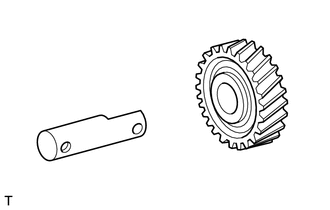
Remove the reverse idler gear shaft from the reverse idler gear.
-