AIR CONDITIONING SYSTEM Heater Water Pump Circuit
DESCRIPTION
The heater accessory assembly feeds engine coolant to the heater core assembly when the hybrid control system is stopped to prevent heating performance from decreasing. The air conditioning amplifier assembly sends the water pump ON request signal to the hybrid vehicle control ECU assembly via CAN communication system. Upon receiving the water pump ON request signal, the hybrid vehicle control ECU assembly activates the No. 1 semiconductor power integration control ECU to operate the heater accessory assembly in accordance with the command from the ECU assembly.
If warm air is not discharge (airflow volume control is normal), the following malfunctions are possible.
| Symptom | Factor |
|---|---|
|
|
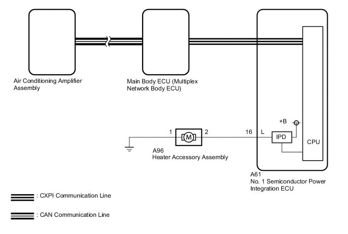
WIRING DIAGRAM
CAUTION / NOTICE / HINT
Note
Before replacing the main body ECU (multiplex network body ECU), refer to PRECAUTION.
PROCEDURE
-
CHECK CAN COMMUNICATION SYSTEM
-
Using the GTS, check if the CAN communication system is functioning normally.
OK CAN communication system DTCs are not output. Result Proceed to OK NG
NG 
GO TO CAN COMMUNICATION SYSTEM Click here
OK 
-
-
CHECK CXPI COMMUNICATION SYSTEM
-
Using the GTS, check if the CXPI communication system is functioning normally.
OK CXPI communication system DTCs are not output. Result Proceed to OK NG
NG
GO TO CXPI COMMUNICATION SYSTEM Click here
OK
-
-
CHECK POWER INTEGRATION SYSTEM
-
Using the GTS, check if the power integration system is functioning normally.
OK Power integration system DTCs are not output. Result Proceed to OK NG
NG
GO TO POWER INTEGRATION SYSTEM Click here
OK
-
-
CHECK HEATER ACCESSORY ASSEMBLY
-
Disconnect the A96heater accessory assembly connector.
-
Connect the GTS to the DLC3.
-
Turn the engine switch on (IG).
-
Turn the GTS on.
-
Enter the following menus: Body Electrical / Air Conditioner / Active Test.
-
Check the operation by referring to the table below.
Body Electrical > Air Conditioner > Active TestTester Display Measurement Item Control Range Diagnostic Note Water Pump Heater accessory assembly ON/OFF
-
Engine switch on (IG)
-
Air conditioning system operating
Body Electrical > Air Conditioner > Active TestTester Display Water Pump -
-
Measure the voltage according to the value(s) in the table below.
Standard Voltage Tester Connection Switch Condition Specified Condition A61-16 (L) - Body ground Perform Active Test and select "OFF" 11 to 14 V Perform Active Test and select "ON" Below 1 V Result Proceed to OK NG
NG
REPLACE AIR CONDITIONING AMPLIFIER ASSEMBLY Click here
OK
-
-
READ VALUE USING GTS (STATUS OF A/C WATER PUMP FUSE)
-
Connect the GTS to the DLC3.
-
Turn the engine switch on (IG).
-
Turn the GTS on.
-
Enter the following menus: Body Electrical / Power Integration No.1 / Data List.
-
Read the Data List according to the display on the GTS.
Body Electrical > Power Integration No.1 > Data ListTester Display Measurement Item Range Normal Condition Diagnostic Note Status of A/C Water Pump Fuse Heater accessory assembly fuse Connect or Disconnect Connect: Fuse not shut off
Disconnect: Fuse shut off
-
Body Electrical > Power Integration No.1 > Data ListTester Display Status of A/C Water Pump Fuse OK The Data List value displays "Connect". Result Proceed to OK NG
NG 
CHECK HEATER ACCESSORY ASSEMBLY Click here
OK
-
-
READ VALUE USING GTS (A/C WATER PUMP INPUT SIGNAL)
-
Connect the GTS to the DLC3.
-
Turn the engine switch on (IG).
-
Turn the GTS on.
-
Enter the following menus: Body Electrical / Power Integration No.1 / Data List.
-
Read the Data List according to the display on the GTS.
Body Electrical > Power Integration No.1 > Data ListTester Display Measurement Item Range Normal Condition Diagnostic Note A/C Water Pump Input Signal Heater accessory assembly input status OFF or ON OFF: Heater accessory assembly does not operate
ON: Heater accessory assembly operates
-
Body Electrical > Power Integration No.1 > Data ListTester Display A/C Water Pump Input Signal OK Display changes according to heater accessory operation. Result Proceed to OK NG
NG
REPLACE MAIN BODY ECU (MULTIPLEX NETWORK BODY ECU) Click here
OK
-
-
READ VALUE USING GTS (A/C WATER PUMP OUTPUT SIGNAL)
-
Connect the GTS to the DLC3.
-
Turn the engine switch on (IG).
-
Turn the GTS on.
-
Enter the following menus: Body Electrical / Power Integration No.1 / Data List.
-
Read the Data List according to the display on the GTS.
Body Electrical > Power Integration No.1 > Data ListTester Display Measurement Item Range Normal Condition Diagnostic Note A/C Water Pump Output Signal Heater accessory assembly output status OFF or ON OFF: Heater accessory assembly does not operate
ON: Heater accessory assembly operates
-
Body Electrical > Power Integration No.1 > Data ListTester Display A/C Water Pump Output Signal OK Display changes according to heater accessory operation. Result Proceed to OK NG
NG
REPLACE NO. 1 SEMICONDUCTOR POWER INTEGRATION ECU Click here
OK
-
-
INSPECT HEATER ACCESSORY ASSEMBLY
-
Remove the heater accessory assembly.
-
Inspect the heater accessory assembly.
Result Proceed to OK NG
NG
REPLACE HEATER ACCESSORY ASSEMBLY Click here
OK
-
-
CHECK HARNESS AND CONNECTOR (HEATER ACCESSORY ASSEMBLY - NO. 1 SEMICONDUCTOR POWER INTEGRATION ECU AND BODY GROUND)
-
Disconnect the A96 heater accessory assembly connector.
-
Disconnect the A61 No. 1 semiconductor power integration ECU connector.
-
Measure the resistance according to the value(s) in the table below.
Standard Resistance Tester Connection Condition Specified Condition A96-2 - A61-16 (L) Always Below 1 Ω A96-1 - Body ground Always Below 1 Ω A96-2 or A61-16 (L) - Other terminals and body ground Always 10 kΩ or higher Result Proceed to OK NG
OK
REPLACE NO. 1 SEMICONDUCTOR POWER INTEGRATION ECU Click here
NG
REPAIR OR REPLACE HARNESS OR CONNECTOR
-
-
CHECK HEATER ACCESSORY ASSEMBLY
-
Disconnect the A96 heater accessory connector.
-
Connect the GTS to the DLC3.
-
Turn the engine switch on (IG).
-
Turn the GTS on.
-
Enter the following menus: Body Electrical / Power Integration No.1 / Data List.
-
Read the Data List according to the display on the GTS.
Body Electrical > Power Integration No.1 > Data ListTester Display Measurement Item Range Normal Condition Diagnostic Note Status of A/C Water Pump Fuse Heater accessory assembly fuse Connect or Disconnect Connect: Fuse not shut off
Disconnect: Fuse shut off
-
Body Electrical > Power Integration No.1 > Data ListTester Display Status of A/C Water Pump Fuse OK The Data List value displays "Connect". Result Proceed to OK NG
NG
REPLACE HEATER ACCESSORY ASSEMBLY Click here
OK
-
-
CHECK HARNESS AND CONNECTOR (HEATER ACCESSORY ASSEMBLY - NO. 1 SEMICONDUCTOR POWER INTEGRATION ECU)
-
Disconnect the A96 heater water pump assembly connector.
-
Disconnect the A61 No. 1 semiconductor power integration ECU connector.
-
Measure the resistance according to the value(s) in the table below.
Standard Resistance Tester Connection Condition Specified Condition A96-2 - A61-16 (L) Always Below 1 Ω A96-2 or A61-16 (L) - Other terminals and body ground Always 10 kΩ or higher Result Proceed to OK NG
OK
REPLACE NO. 1 SEMICONDUCTOR POWER INTEGRATION ECU Click here
NG
REPAIR OR REPLACE HARNESS OR CONNECTOR
-