INSTRUMENT PANEL SAFETY PAD DISASSEMBLY
PROCEDURE
-
REMOVE INSTRUMENT PANEL PASSENGER AIRBAG ASSEMBLY
w/o Occupant Classification System:
w/ Occupant Classification System:
-
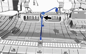
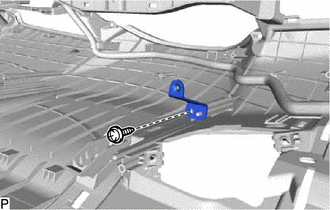
REMOVE NO. 1 SIDE DEFROSTER NOZZLE DUCT
-
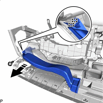

Remove in this Direction Remove the screw <E>.
-
Disengage the 2 guides as shown in the illustration.
-
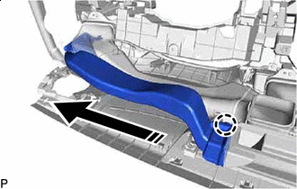
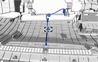
Remove in this Direction Disengage the claw to remove the No. 1 side defroster nozzle duct as shown in the illustration.
-
-
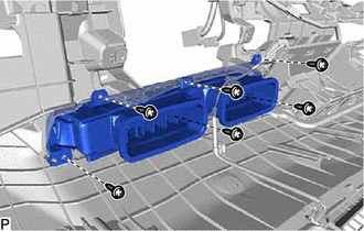
REMOVE NO. 2 SIDE DEFROSTER NOZZLE DUCT
-
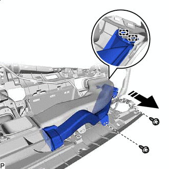
Remove in this Direction Remove the 2 screws <E>.
-
Disengage the 2 guides as shown in the illustration.
-
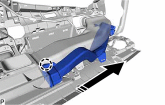
Remove in this Direction Disengage the claw to remove the No. 2 side defroster nozzle duct as shown in the illustration.
-
-
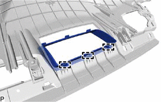
REMOVE DEFROSTER NOZZLE ASSEMBLY
-
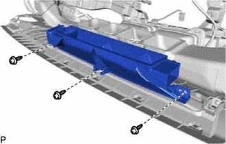
Remove the 3 screws <E> and defroster nozzle assembly.
-
-
REMOVE METER MIRROR SUB-ASSEMBLY (w/ Headup Display)
-
REMOVE NO. 1 HEATER TO REGISTER DUCT SUB-ASSEMBLY
-
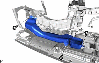
Remove the 3 screws <E> and No. 1 heater to register duct sub-assembly.
-
-
REMOVE NO. 3 HEATER TO REGISTER DUCT SUB-ASSEMBLY
-
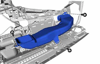
Remove the 3 screws <E> and No. 3 heater to register duct sub-assembly.
-
-
REMOVE ANTENNA CORD SUB-ASSEMBLY (w/ Navigation Antenna)
-
REMOVE NAVIGATION ANTENNA ASSEMBLY WITH BRACKET (w/ Navigation Antenna)
-
REMOVE ANTENNA DIVIDER (w/ Telematics Transceiver)
-
REMOVE ANTENNA CORD SUB-ASSEMBLY (w/ Telematics Transceiver)
-
REMOVE NO. 2 HEATER TO REGISTER DUCT SUB-ASSEMBLY
-
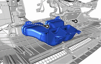
Remove the 2 screws <E> and No. 2 heater to register duct sub-assembly.
-
-
REMOVE AUTOMATIC LIGHT CONTROL SENSOR
-
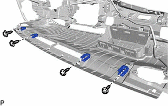
REMOVE NO. 2 INSTRUMENT PANEL REGISTER ASSEMBLY
-
Disconnect the connector.
-
Remove the 6 screws <E> and No. 2 instrument panel register assembly.
-
-
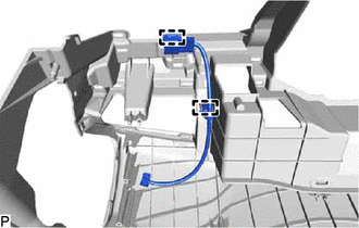
REMOVE NO. 3 INSTRUMENT PANEL WIRE
-
Disengage the clamp to remove the No. 3 instrument panel wire.
-
-
REMOVE NO. 1 METER BRACKET SUB-ASSEMBLY
-
Remove the screw <E> and No. 1 meter bracket sub-assembly.
-
-
REMOVE NO. 2 METER BRACKET SUB-ASSEMBLY (w/ Headup Display)
-
Remove the screw <E> and No. 2 meter bracket sub-assembly.
-
-
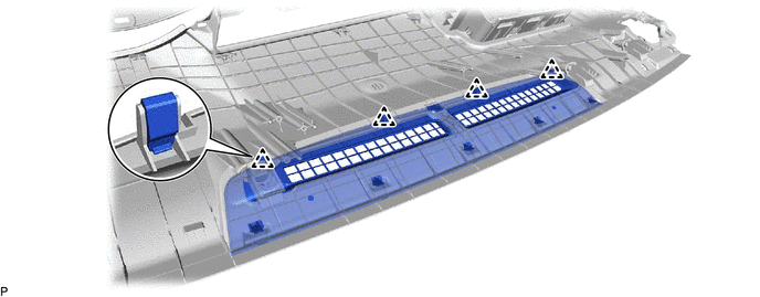
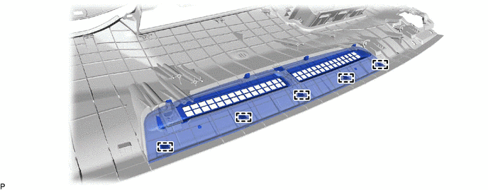
REMOVE NO. 1 DEFROSTER NOZZLE GARNISH
-
Disengage the 4 clips.
-
Disengage the 5 guides to remove the No. 1 defroster nozzle garnish.
-
-
REMOVE INSTRUMENT PANEL HOLE COVER (w/ Headup Display)
-
Disengage the 5 claws.
-
Disengage the 3 guides to remove the instrument panel hole cover.
-
-
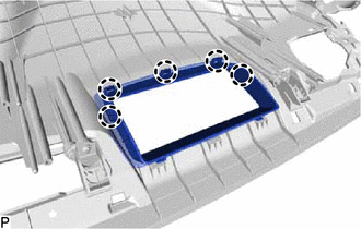
REMOVE NO. 1 INSTRUMENT PANEL PIN
-
Remove the 4 screws <E> and 4 No. 1 instrument panel pins.
-
-
REMOVE ANTENNA CORD SUB-ASSEMBLY (for LHD)
-
REMOVE ANTENNA CORD SUB-ASSEMBLY (for RHD)
-
REMOVE AIR DUCT SUB-ASSEMBLY (w/ Ion Generator)
for RHD:
-
REMOVE ION GENERATOR WITH BRACKET (w/ Ion Generator)
-
REMOVE NO. 4 INSTRUMENT PANEL WIRE (w/ Ion Generator)
-
Disengage the 2 clamps to remove the No. 4 instrument panel wire.
-
-
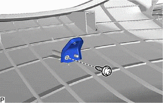
REMOVE INSTRUMENT PANEL CUSHION
-
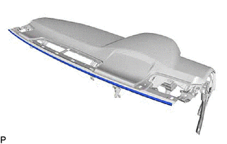
Remove the instrument panel cushion.
-