THEFT DETERRENT SYSTEM, Diagnostic DTC:B2764
| DTC Code | DTC Name |
|---|---|
| B2764 | Short to GND in Intrusion Sensor Signal Circuit |
DESCRIPTION
The intrusion sensor (theft warning ultrasonic sensor) conducts self-diagnosis immediately after power is supplied to the sensor (when the theft deterrent system is set).
If a malfunction is detected in the ISIF line, the main body ECU (multiplex network body ECU) stores this DTC.
DTC No. |
Detection Item |
DTC Detection Condition |
Trouble Area |
|---|---|---|---|
B2764 |
Short to GND in Intrusion Sensor Signal Circuit |
|
|
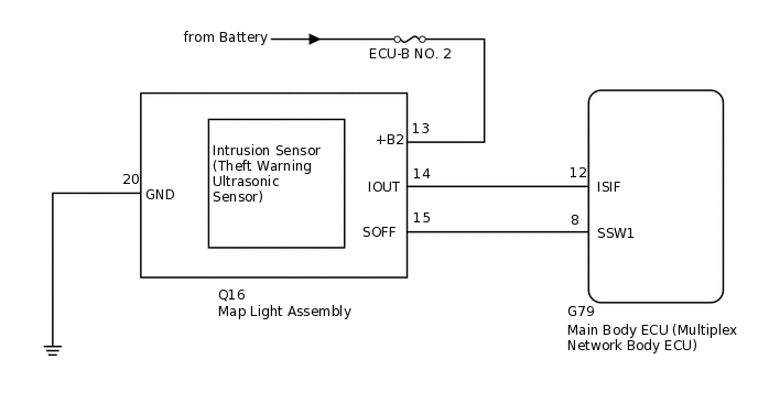
WIRING DIAGRAM
CAUTION / NOTICE / HINT
Inspect the fuses for circuits related to this system before performing the following inspection procedure.
When replacing the main body ECU (multiplex network body ECU), make sure to replace it with a new one.
PROCEDURE
CHECK WAVEFORM (INTRUSION SENSOR [THEFT WARNING ULTRASONIC SENSOR]) (IOUT)
Using an oscilloscope, check the waveform.
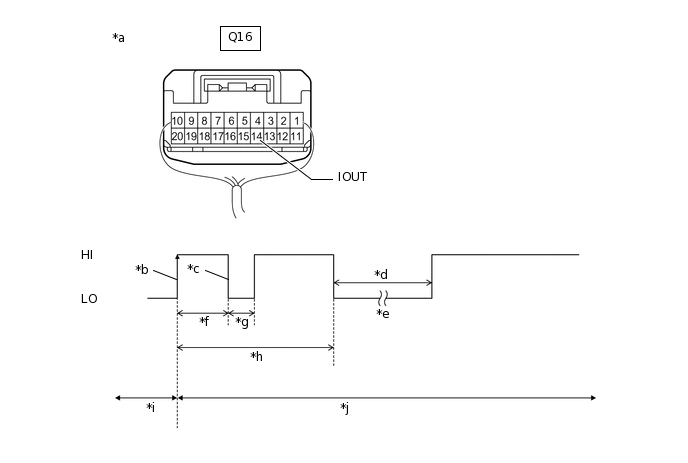
*a
Component with harness connected
(Map Light Assembly)
*b
IOUT Initial Signal
*c
IOUT Initial Response
*d
Approximately 1.0 seconds
*e
Initial Diagnosis
*f
Approximately 1.0 to 1.6 seconds
*g
Approximately 0.05 seconds
*h
Approximately 5.5 seconds
*i
Disarmed State
*j
Arming Preparation State
*k
HI
*l
LO
Table 1. Measurement Condition Tester Connection
Content
Tester Connection
Q16-14 (IOUT) - Body ground
Tool Setting
2 V/DIV., 100 ms./DIV.
Condition
Theft deterrent system is set (system changes from disarmed state to arming preparation state)
Tip:If the intrusion sensor (theft warning ultrasonic sensor) is normal, an initial response is output in response to the HI input from the main body ECU (multiplex network body ECU).
If the waveform output remains LO, there may be a problem with the main body ECU (multiplex network body ECU), as there is no input from the main body ECU (multiplex network body ECU).
OK
The waveform displays properly (HI is 6.5 V or higher and LO is below 1 V).
Result
Proceed to
OK
NG
CHECK VOLTAGE (INTRUSION SENSOR [THEFT WARNING ULTRASONIC SENSOR]) (IOUT)
-
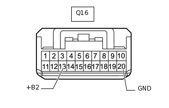
*a
Front view of wire harness connector
(to Map Light Assembly)
Disconnect the map light assembly connector.
Measure the voltage according to the value(s) in the table below.
Standard Voltage
Tester Connection
Condition
Q16-14 (IOUT) - Q16-20 (GND)
Immediately after theft deterrent system set
Result
Result
Proceed to
IOUT voltage is below 1 V when theft deterrent system is set
A
IOUT voltage is 6.5 V or higher when theft deterrent system is set
B
Tip:With connector Q16 of the map light assembly disconnected, measure the voltage at IOUT when the theft deterrent system is set.
B REPLACE MAP LIGHT ASSEMBLYClick here
-
CHECK HARNESS AND CONNECTOR (MAIN BODY ECU [MULTIPLEX NETWORK BODY ECU] - MAP LIGHT ASSEMBLY)
Disconnect the G79 main body ECU (multiplex network body ECU) connector.
Disconnect the Q16 map light assembly connector.
Measure the resistance according to the value(s) in the table below.
Standard Resistance
Tester Connection
Condition
Specified Condition
G79-12 (ISIF) - Q16-14 (IOUT)
Always
Below 1 Ω
G79-12 (ISIF) - Body ground
Always
10 kΩ or higher
Q16-14 (IOUT) - Body ground
Always
10 kΩ or higher
Result
Proceed to
OK
NG
NG REPAIR OR REPLACE HARNESS OR CONNECTOR
REPLACE MAP LIGHT ASSEMBLY
Temporarily replace the map light assembly with a new or normally functioning one.
Result
Proceed to
NEXT
CHECK FOR DTC
Clear the DTCs.
Body Electrical > Main Body > Clear DTCs
Turn the ignition switch to ON, then off.
Set the theft deterrent system to "ARMED STATE".
Check that the security indicator changes from illuminated to blinking.
Set the theft deterrent system to "DISARMED STATE".
Check for DTCs.
Body Electrical > Main Body > Trouble Codes
Result
Proceed to
DTC B2764 is not output
DTC B2764 is output
DTC B2764 is not output END (MAP LIGHT ASSEMBLY WAS DEFECTIVE)