SLIDING ROOF SYSTEM Sliding Roof ECU Power Source Circuit
| DTC Code | DTC Name |
|---|---|
| Sliding Roof ECU Power Source Circuit |
DESCRIPTION
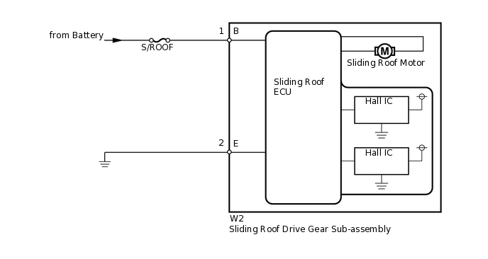
If the sliding function and tilt function do not operate, there may be a malfunction in the sliding roof drive gear sub-assembly power source circuit.
WIRING DIAGRAM
CAUTION / NOTICE / HINT
When the sliding roof drive gear sub-assembly is removed and reinstalled or replaced, the sliding roof drive gear sub-assembly must be initialized (Click here).
Inspect the fuses for circuits related to this system before performing the following inspection procedure.
PROCEDURE
CHECK HARNESS AND CONNECTOR (SLIDING ROOF ECU - BATTERY AND BODY GROUND)
-
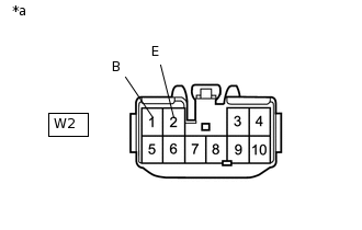
*a
Front view of wire harness connector
(to Sliding Roof Drive Gear Sub-assembly)
Disconnect the W2 ECU connector.
Measure the resistance and voltage according to the value(s) in the table below.
Standard Resistance
Tester Connection
Condition
Specified Condition
W2-2 (E) - Body ground
Always
Below 1 Ω
Standard Voltage
Tester Connection
Condition
Specified Condition
W2-1 (B) - Body ground
Always
11 to 14 V
Result
Result
OK
NG
NG REPAIR OR REPLACE HARNESS OR CONNECTOR
-